272 Rockwell Automation Publication 7000L-UM301F-EN-P - March 2020
Chapter 5 Component Definition and Maintenance
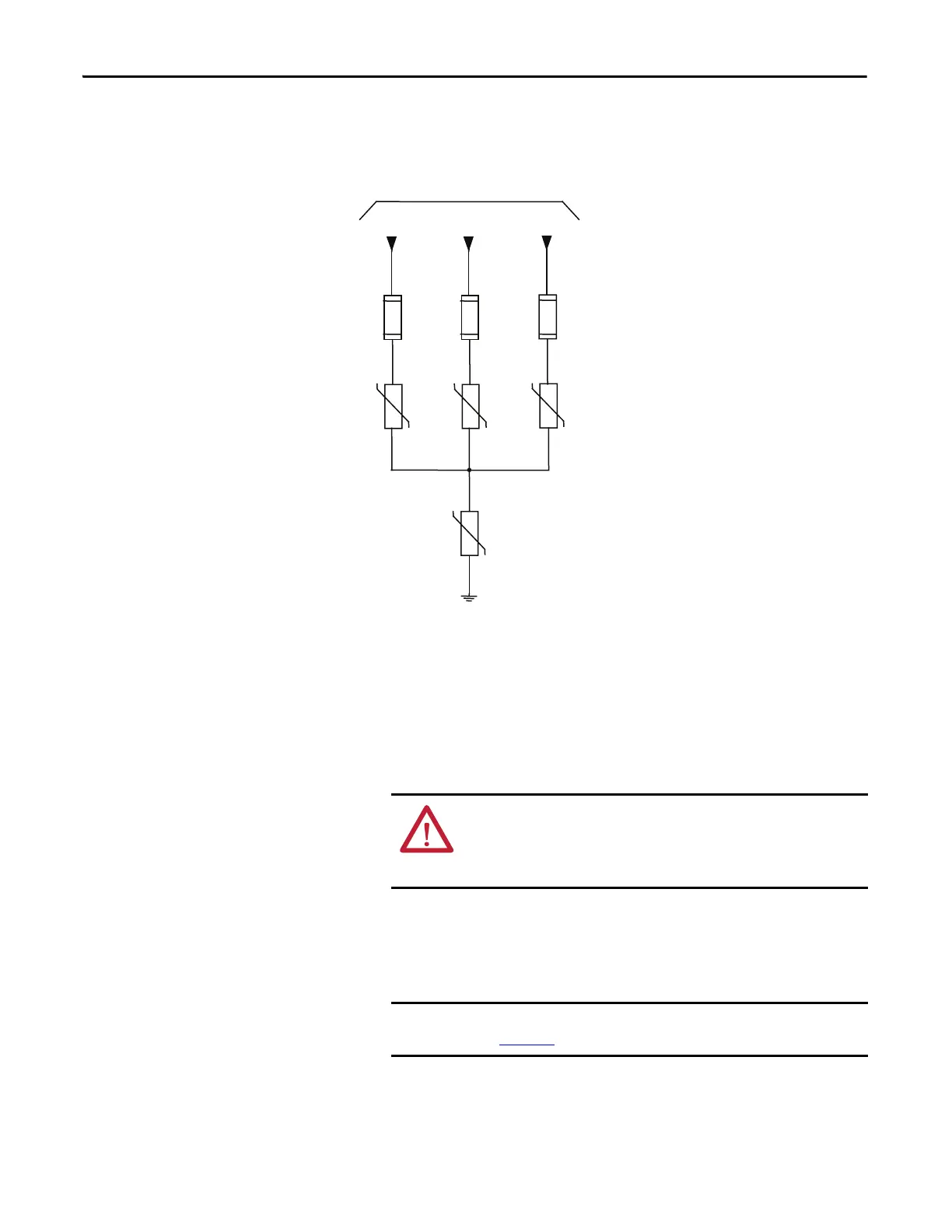
Figure 225 - Simplified Wiring Diagram
Transient Suppression
Network Fuse Replacement
Two sizes of fuses (5 kV, 7.2 kV) are available within the Transient Suppression
Network (TSN) located inside the connection cabinet. The 18 Pulse drive
contains three TSNs.
1. Ensure there is no power to the equipment.
2. Fuses are held in a place with a fuse clip. To remove the fuse pull firmly.
3. To replace the fuse, hold it in position and push firmly until the fuse is
seated within the fuse clip. Install fuses so that the rating is visible.
U
V
W
Drive Input Power
from
Line Terminals
Transient Suppression Network
Medium Voltage Input Fuses
Phase MOV
Suppressor
Ground MOV
Suppressor
ATTENTION: To prevent electrical shock, ensure the main power has
been disconnected before working on the drive. Verify that all circuits
are voltage free using a hot stick or appropriate voltage-measuring
device. Failure to do so may result in injury or death.
Make sure to replace the fuse with another of the same rating. (See
Figure 226
for location.)

 Loading...


