Rockwell Automation Publication 7000L-UM301F-EN-P - March 2020 385
Component Definition and Maintenance Chapter 5
Diagnostic Setup
The diagnostic setup is used to define the source of the diagnostic trigger.
Information that must be programmed in the diagnostic setup is listed in
Table 2 9
.
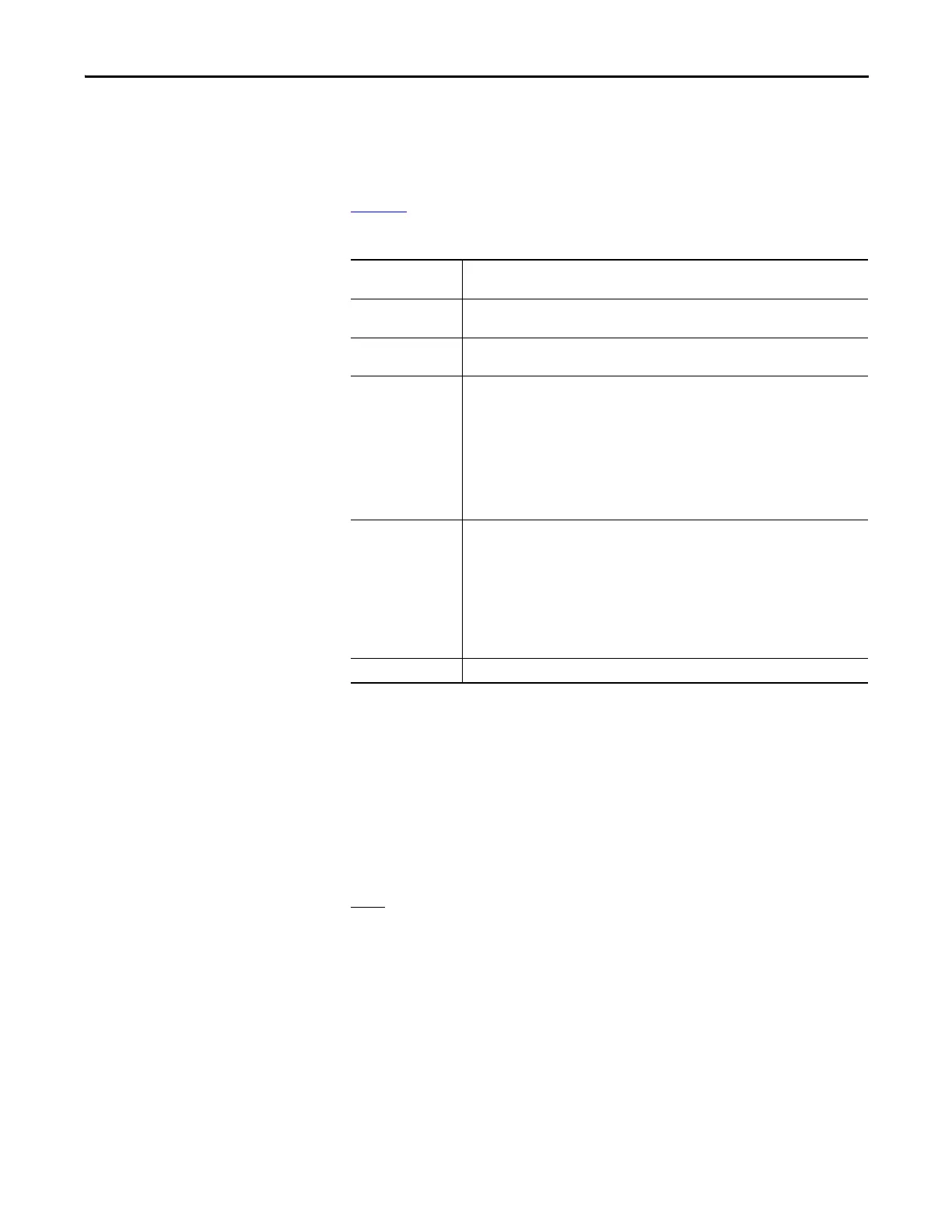
Table 29 - Diagnostic Setup
Setting up the Trend
The Access level must be Basic or higher level before programming the drive’s
trending feature. To change Access level to Basic, press F10 [Access] key on the
main screen. The display will change to ‘Access’ screen. Select Basic by pressing
down-arrow key and then press Enter key. The Access level will change to Basic.
Press F10 [EXIT} key again to exit to the main screen.
Note
: The parameter assigned to Tr a c e 1 is used for trigger purpose. The
Condition and Data defined in steps 11 and 12 must be satisfied for the trend to
trigger. In most cases the parameter 569 “DrvStatus Flag1”is assigned to Trace1
for trigger purpose. A value of 18 Hex for Data (Step-12 below) is used to
capture the trend when the drive detects either an Alarm or a Fault condition. If
you are interested in the fault condition only then set Data as 8 Hex. If you are
interested in Alarm condition only then set Data as 10 Hex.
You can reset the Alarm or Fault in the drive, but don’t Re-Arm the trend until
you print (upload) the trend data into your laptop. Print the Alarm Queue as
well, so that you know which alarm or fault condition was detected by the drive.
Trace The Read-Only Parameter which is assigned to a particular list. The item linked to Trace 1 is
used as the trigger value. There are 16 traces in total, although not all have to be active.
Rate The time delay between sample periods. Any value between 0...20,000 msec can be set. Use
numeric keypad to enter the value and press the enter key to accept.
Post The percentage of the list which will occur after the after the trigger point. Any value
between 0...100% may be used.
Trigger Defines whether you want a continuous or a single-shot trigger. Pressing this key will place
an S or a C in front of the trigger parameter. You will almost always want a Single-Shot (S)
trigger.
S = Single shot. The trigger occurs only once and stops. The trigger must be manually re-
armed. The Re-Arm function clears the memory buffer, which contains the data stored from
the previous trend. It is necessary to reset the trending feature in order for a second trigger to
occur, unless you have continuous trigger enabled.
C = Continuous capture. Auto re-arm is enabled to collect new trends until stopped by
viewing contents of captured data.
Cond Defines the condition that will cause the trigger. Possible options are:
Data Defines the trigger value with respect to the read-only parameter in Trace 1.
= Equal to + Boolean OR
N= Not equal to N+ Boolean NOR
> Greater than & Boolean AND
< Less than N& Boolean NAND

 Loading...


