Rockwell Automation Publication 7000L-UM301F-EN-P - March 2020 365
Component Definition and Maintenance Chapter 5
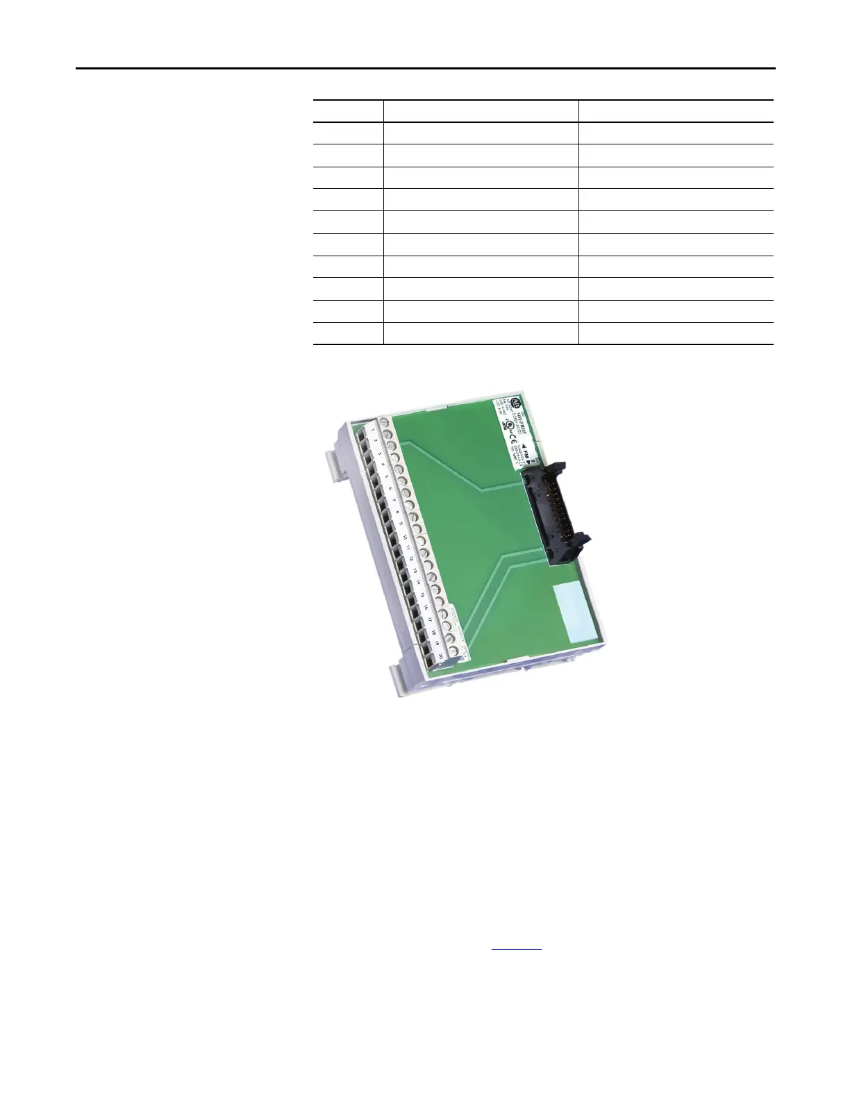
Figure 300 - 20-pin Interface Module (IFM)
Quadrature Encoder Operation
The Universal Encoder Interface will accept either single or dual quadrature
encoders. Configuration of the board to accept the encoders is done through
jumpers on J4.
Boards shipped from the factory come defaulted to single quadrature encoder
configuration.
(1)
For dual encoder configurations, the primary encoder is wired to pins 1 to 7 on
the 1492-IFM20 module. (See Table 2 6
).
11 B2+ (Redundant or Dual ENC) E8
12 B2- (Redundant or Dual ENC) E9
13 Z2+ (Redundant or Dual ENC) E10
14 Z2- (Redundant or Dual ENC) E11
15 ENC_COM ENC_COM
16 ENC_COM ENC_COM
17 ENC_COM ENC_COM
18 ENC PWR (+12V) ENC PWR (+12V)
19 ENC PWR (+12V) ENC PWR (+12V)
20 ENC PWR (+12V) ENC PWR (+12V)
(1) Consult factory for availability of dual Quadrature Encoder options.
IFM Pin # Quadrature Encoder Function Absolute Encoder Function

 Loading...


