Rockwell Automation Publication 7000L-UM301F-EN-P - March 2020 273
Component Definition and Maintenance Chapter 5
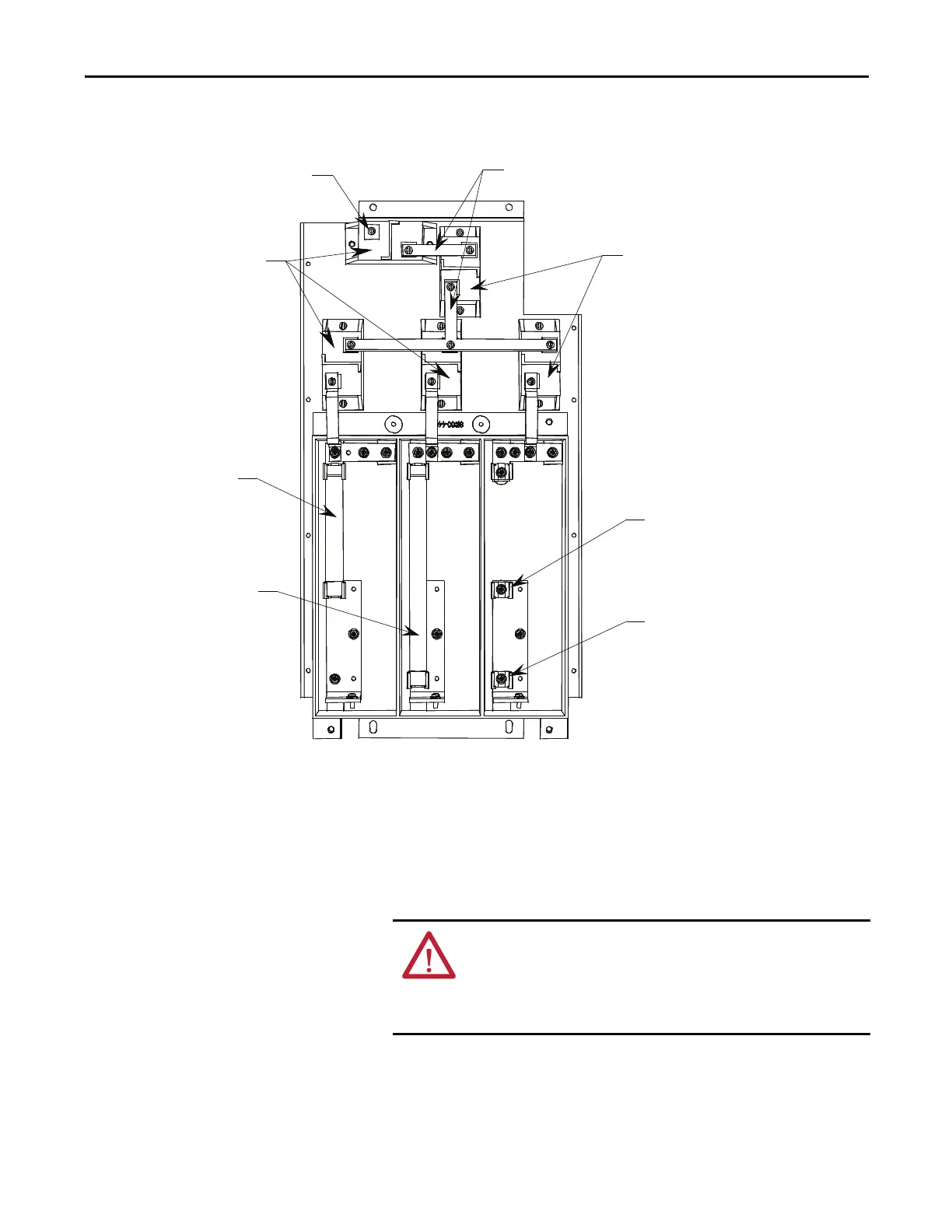
Figure 226 - Transient Suppression Network
Metal-Oxide Varistor
Replacement
Metal-oxide varistors (MOV) are part of the Transient Suppression Network
located within the connection cabinet.
1. Ensure there is no power to the equipment.
2. Observe the locations of the connecting links.
3. Detach the connecting links by removing the screws.
4. Using a screwdriver remove the screws at the base.
7.2 kV fuses
5kV fuses
Varistors
Location of ground
Connecting links
Varistors
Location for 7.2 kV fuses
Location for 5 kV fuses
ATTENTION: To prevent electrical shock, ensure the main power has
been disconnected before working on the transient suppression
network. Verify that all circuits are voltage free using a hot stick or
appropriate voltage-measuring device. Failure to do so may result in
injury or death.

 Loading...


