Rockwell Automation Publication 7000L-UM301F-EN-P - March 2020 349
Component Definition and Maintenance Chapter 5
Printed Circuit Board
Replacement
The replacement of printed circuit boards should be handled in a careful manner.
There are some basic precautions that should be taken. They include the
following:
• Remove all power to the drive.
• Do not remove the replacement board from the anti-static bag until
necessary.
• Use anti-static wrist strap, grounded in the Low Voltage Control Section.
There are no direct screw/terminal connections on any of the Low Voltage circuit
boards. All wire/terminal connections are made with plugs that plug into the
circuit boards. This means that changing boards only requires the removal of the
plugs, minimizing the chance of mistakes when reconnecting all of the wiring.
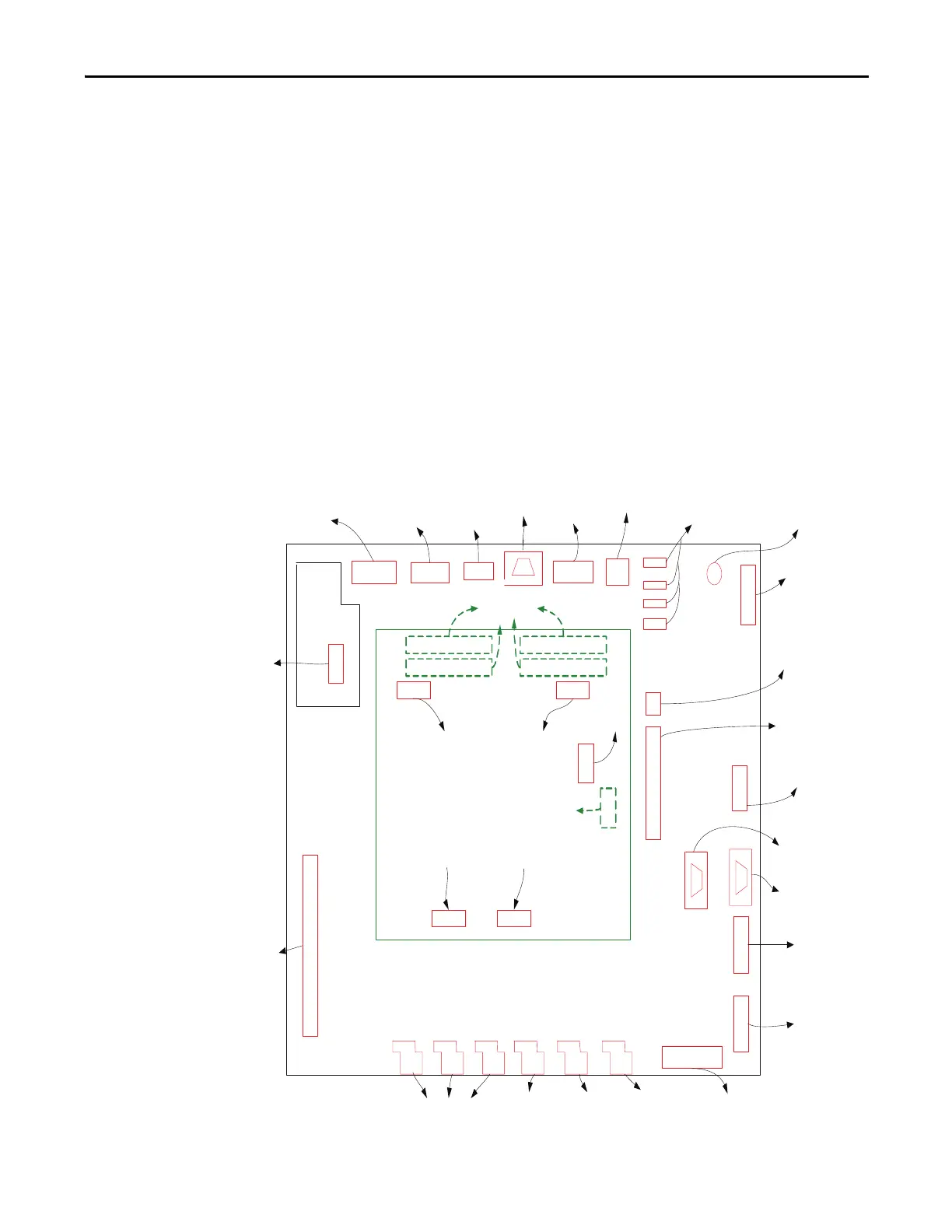
IO Connectors on Control Boards
Figure 290 - IO Connectors on Control Boards
J2
J3
J4
J5
J6
J7
J8
LINE CURRENT INP UTS
MOTOR
CURRE NT
INPUTS
DC LIN K
CURRE NT
INPUTS
GROUND FA UL T &
CMC NEUTRAL
CURR ENT INPUTS
ISOLATED & NON-ISOLATED
ANALOG INPUTS AND
NON-ISOLATED OUTPUTS
J9
J10
AIR PRESS URE
INPUTS
METER
OUTP UTS &
SPEE D POT
INPUT
J12
J11
COMM S CONN ECTIONS
TERMINAL (PA NEL VIEW)
J14
J16
DC P OWE R S UPP L Y
MONITORING
5V1 , 5V2 & DC-BUS+
DPI
INTERFACE
J17
COMMS
CONN ECTIONS
DPI/SCANPORT
J15
J13
J21
J20
J19
J18
J22J2 3
J25
J26J27
J28
J1
DC FAIL SIGNAL
MONITORING
XIO-PWR(+24V),+/-15V,+/-24V
+5V DIG, DC POWER SUPPLIES
DC -AB U S +5 6V
OUTPUT MONITORING
(IN UPS OP TION)
CONN ECTION
XIO BOARD
CONNECTION
PA RALLEL
DR IV E
UPS FAIL
SIGNAL
MONITORING
LINE VOLTAGE
SYNC. TRANSFER
FEE DBA CK INPUTS
MOTOR &LINE
DC LI NK A ND
NEUTRAL POINT
VOLTAGE INTPUTS
OO &
AC VOLTAGE
FEE DBA CK INPUTS
ENCODER
INTERFACE
CONTROL I/O
STATUS &
CONTROL
POWER
MONITORING
DPM
J34 J33
J30 J31
DPM-ENCODER
DPM - FASULTS &
OTHE R I/O
DPM - A/D SUB
SYS TEM
DPM - DAC’S SE RIAL
DATA
COMM S CONN ECTIONS
PRINTER OUTPUTS
J24
J32
DPM
POWER SUPPLY
DPM
J4
DOWNLOAD
FIRMWARE
DPM-J11
DPM-J10
DPM-J12
DPM-J13
CONN ECT TO OIBB ,
GET GA TING SIGNA LS
ACB

 Loading...


