308 Rockwell Automation Publication 7000L-UM301F-EN-P - March 2020
Chapter 5 Component Definition and Maintenance
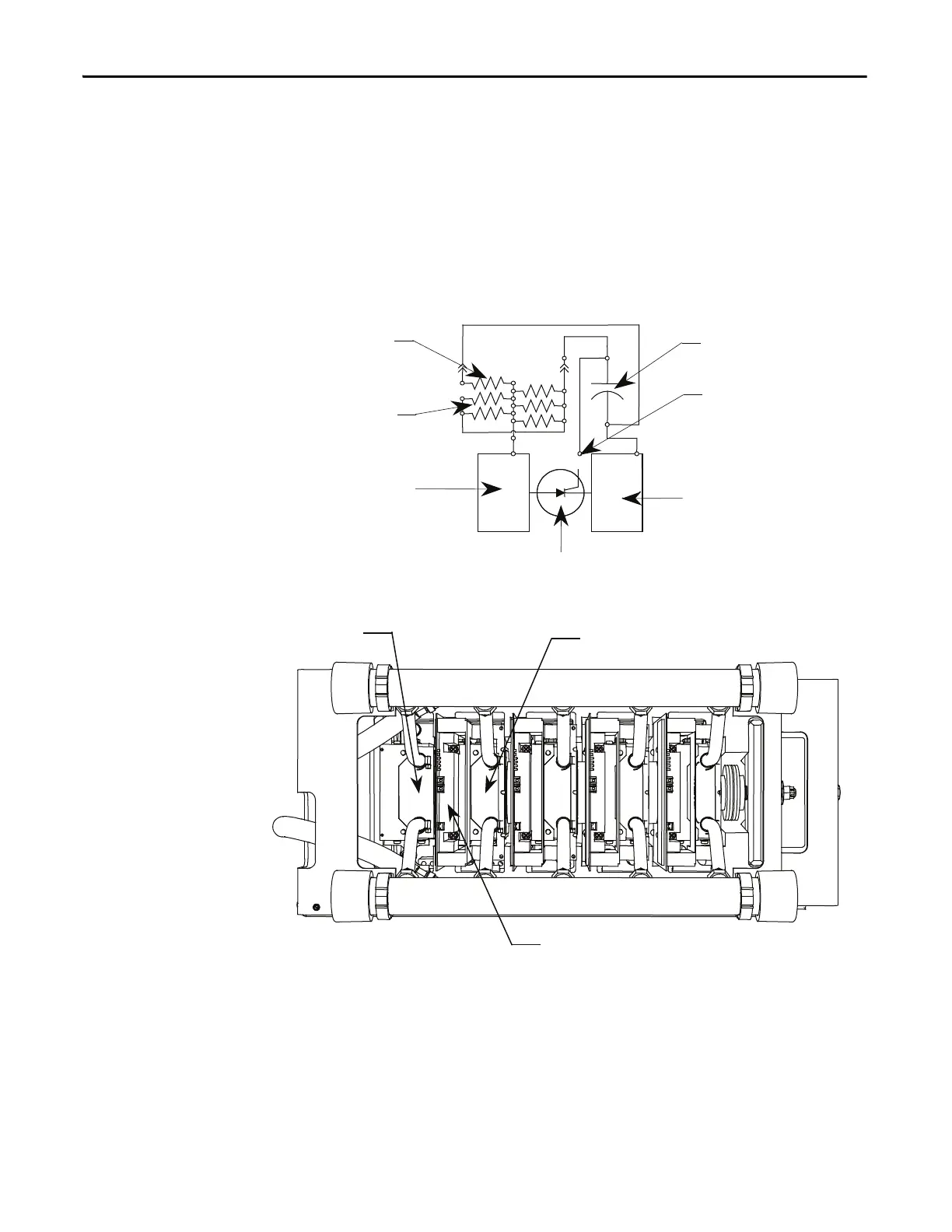
Testing Sharing Resistors
SGCT PowerCages
To determine the sharing resistor value, simply measure the resistance between
the anode and cathode chill blocks. A value between 60 kΩ and 75 kΩ indicates
a good sharing resistor.
Figure 256 - SGCT Power Cage
SCR PowerCages
To obtain the sharing resistor value, disconnect the 2-pole plug of the self-
powered gate driver board labeled SHARING and SNUBBER on the circuit
board. The red wire of the plug is the sharing resistor. Measure the resistance
between the red wire of the plug and the chill block to the left (the anode chill
block). A value of approximately 80 kΩ indicates a healthy sharing resistor.
SGCT
Cathode Chill Block
Anode Chill Block
SGCT
Sharing Resistor
Snubber Resistors
Anode Chill block
Cathode Chill block
Test Point
Snubber Capacitor

 Loading...


