Rockwell Automation Publication 7000L-UM301F-EN-P - March 2020 23
Overview of Drive Chapter 1
Specifications
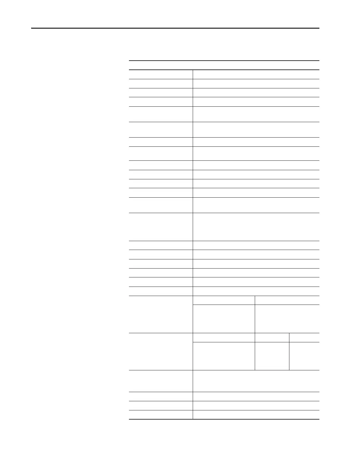
Table 1 - General Design Specifications
Description
Motor Type Induction or Synchronous
Input Voltage Rating 2400V, 3300V, 4160V, 6600V
Input Voltage Tolerance ± 10% of Nominal
Voltage Sag
(1)
-30%
Control Power Loss Ride-through 5 Cycles (Std)
> 5 Cycles (Optional UPS)
Input Protection
(2)
Surge Arrestors (AFE/Direct-to-Drive)
Metal Oxide Varistor (MOV) (18 Pulse)
Input Frequency 50/60 Hz, ±5%
Power Bus Input Short-circuit
Current Withstand (2400…6600V
(3)
)
25 kA RMS SYM, 5 Cycle
Basic Impulse Level
(4)
45 kV (0…1000 m)
Power Bus Design Copper - Tin plated
Ground Bus Copper - Tin plated 6 x 51 mm (¼ x 2 in.)
Customer Control Wire Way Separate and Isolated
Input Power Circuit Protection
(5)
Vacuum Contactor with Fused Isolating Switch
or Circuit Breaker
Output Voltage 0…2400V
0…3300V
0…4160V
0…6000V, 0…6300V, 0…6600V
Inverter Design PWM
Inverter Switch SGCT
Inverter Switch Failure Mode Non-rupture, Non-arc
Inverter Switch Failure Rate (FIT) 100 per 1 Billion Hours Operation
Inverter Switch Cooling Double Sided, Low Thermal Stress
Inverter Switching Frequency 420…440 Hz
Number of Inverter SGCTs Voltage SGCTs (per phase)
2400V
3300V
4160V
6600V
2
4
4
6
Inverter PIV Rating
(Peak Inverse Voltage)
Voltage PIV (each device) Total PIV
2400V
3300V
4160V
6600V
6500V
6500V
6500V
6500V
6500V
13,000V
13,000V
19,500V
Rectifier Designs Direct-to-Drive (transformerless AFE rectifier)
AFE with separate isolation transformer
18 Pulse with separate isolation transformer
Rectifier Switch SCR (18 Pulse), SGCT (AFE Rectifier)
Rectifier Switch Failure Mode Non-rupture, Non-arc
Rectifier Switch Failure Rate (FIT) 50 (SGCT) 100 (SCR) per 1 Billion Hours Operation

 Loading...


