210 Rockwell Automation Publication 7000L-UM301F-EN-P - March 2020
Chapter 4 Commissioning
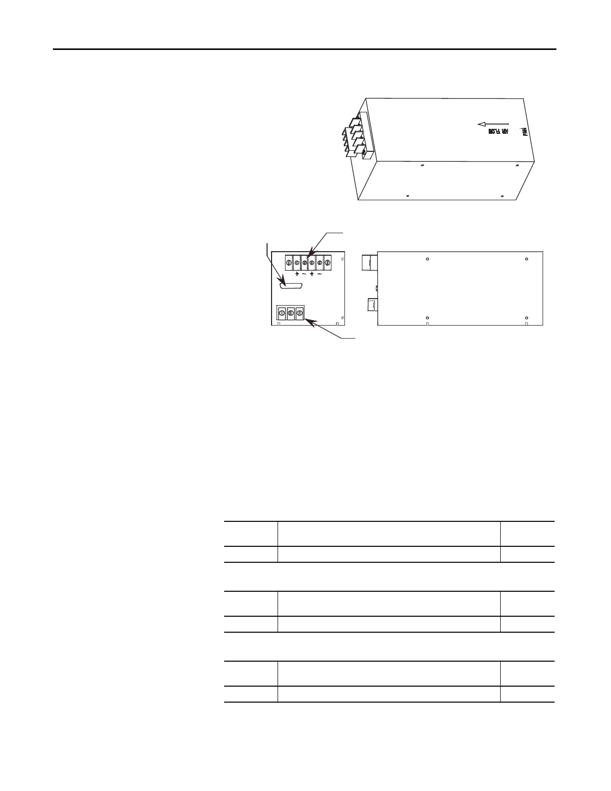
Figure 192 - Location of AC/DC Power Supply on Low Voltage Panel
DC/DC Converter (PS2)
The DC/DC converter has no provision for output power adjustments. A green
LED on front case of the power supply indicates that the power supply is
functioning properly. Using a digital multimeter, measure each of the outputs of
the DC/DC converter to ensure that they meet the values specified on the
electrical schematics. Compare these measured values to those displayed on the
Operator Terminal under the Metering group.
Table 8 - Plug 1 (P1) – INPUT
Table 9 - Plug 2 (P2) – SENSE SIGNAL
Table 10 - Plug 3 (P3) – ISOLATOR
Terminal
Numbers
Description Value
1
→ 2Input Power (+56 V)
Terminal
Numbers
Description Value
Terminal
Numbers
Description Value
1 → 2 ISOLATOR (+24V,1A)--ISOL_COMM (COM4) ±5%
Control signals
DC o utputs
Single phase input
TOP
VIEW
FRONT VIEW
Earth
Line
Neutral

 Loading...


