Rockwell Automation Publication 7000L-UM301F-EN-P - March 2020 311
Component Definition and Maintenance Chapter 5
Snubber Capacitor
Replacement
The snubber capacitors are part of the capacitor assembly located behind the
PowerCage module.
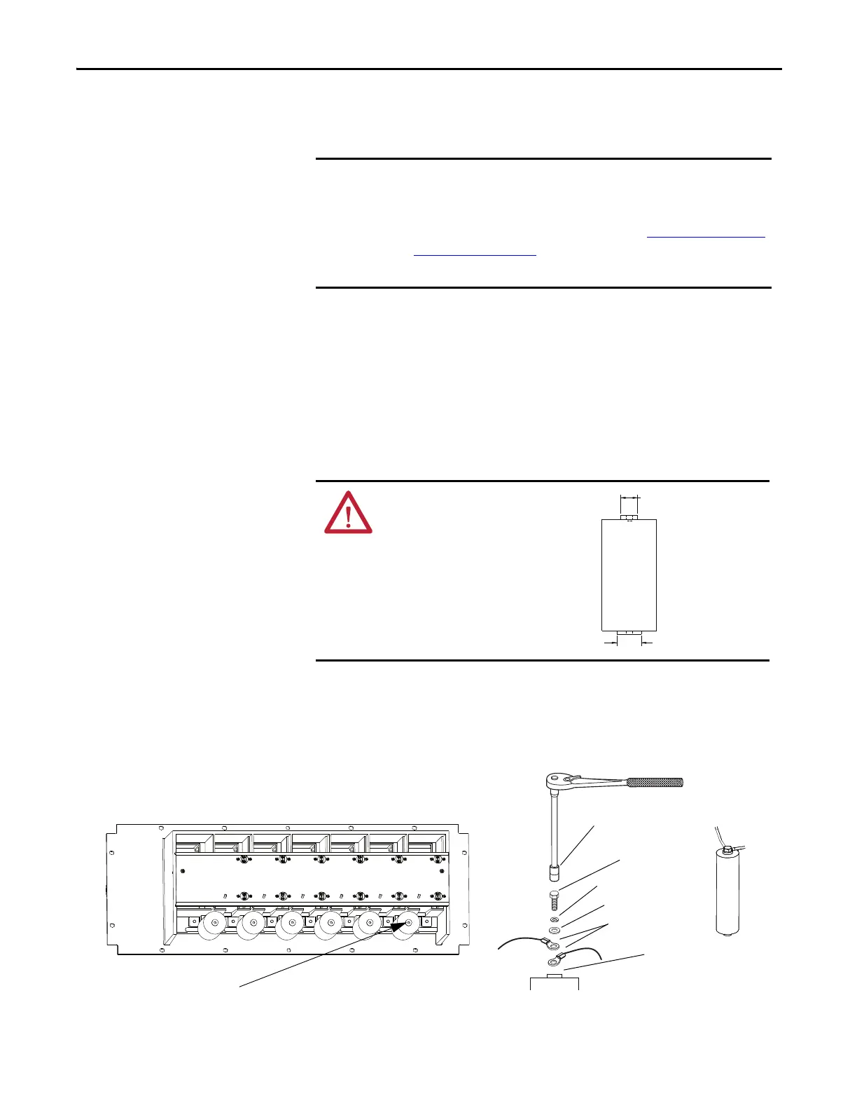
1. Using a 13 mm socket wrench, remove the M8 bolt on the end of the
capacitor and retain hardware.
2. Hand rotate the capacitor counter-clockwise to unscrew it from the
threaded stud connecting it to the PowerCage module.
3. Apply a drop of Loctite 425 to the thread of the 25 mm flange side of the
replacement capacitor.
4. Hand-tighten the replacement capacitor onto the threaded stud.
5. Connect the electrical leads and hardware on the 17 mm flange side of the
replacement capacitor.
Torque M8 hardware to 7 N•m (60 lb•in).
Figure 259 - Rear View of 7000L PowerCage
6. Bundle and secure the connecting wires using wire ties.
IMPORTANT If the drive can be accessed from the rear, the snubber capacitors can be
removed and replaced from the rear, with the PowerCage modules in place.
If the drive cannot be accessed from the rear, the PowerCage modules must
be removed to access the snubber capacitors. See PowerCage Removal and
Replacement on page 305.
Replace the capacitors one at a time. Do not remove all at once.
ATTENTION: You must insert the
capacitor in the correct
orientation.
The 25 mm flange must be
connected to the threaded stud on
the PowerCage module.
17 mm (0.67 in.)
25 mm (0.98 in.)
M8 Hardware Location
M8 Bolt
5/16 in. Lock Washer
5/16 in. Flat Washer
Electrical Leads
13 mm Socket
17 mm Flange

 Loading...


