Rockwell Automation Publication 7000L-UM301F-EN-P - March 2020 59
Drive Installation Chapter 2
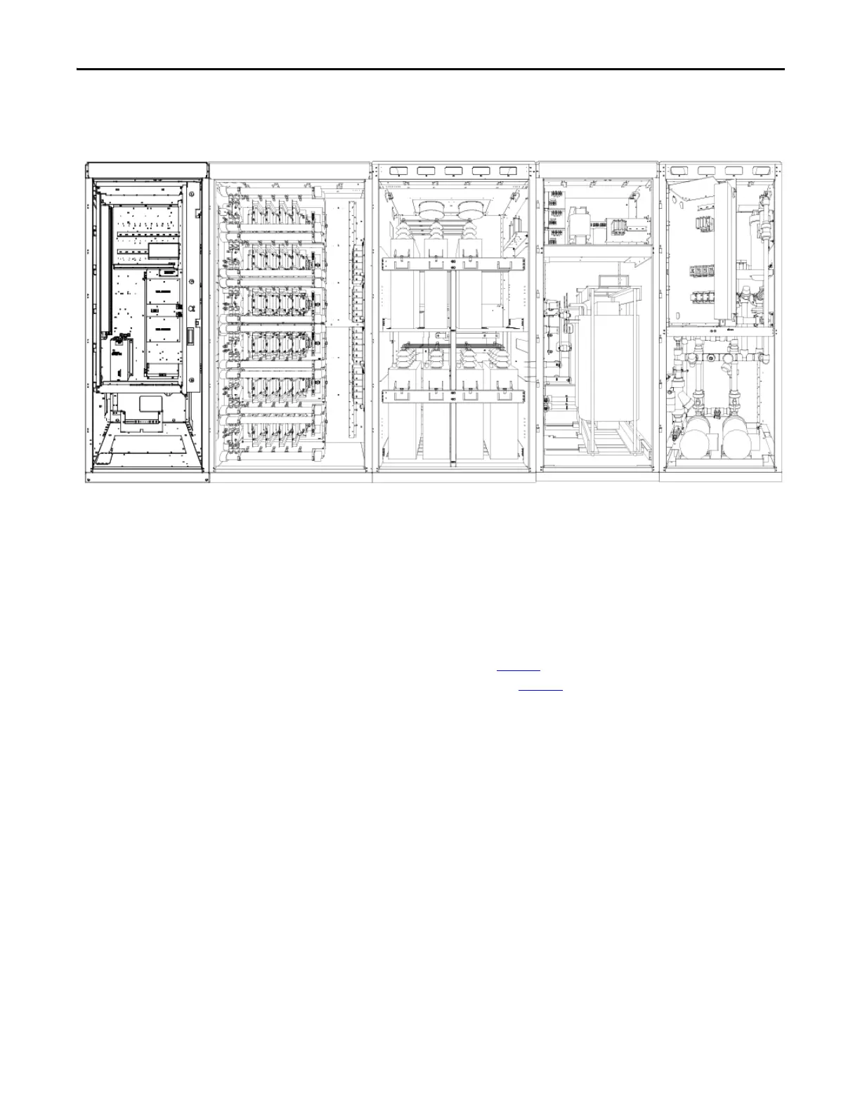
Typical PowerFlex 7000L Drive Structure Layout
Figure 48 - Typical PowerFlex 7000 “C” Frame Drive Structure Layout
Control/Cabling Cabinet
Shows the medium voltage area located in the control/cabling cabinet behind the
low voltage compartment and with barriers removed.
Major Components
The following seven diagrams show the typical layout of each cabinet for
PowerFlex 7000 “C” Frame Drives.
Control and
Cabling Cabinet
Converter Cabinet
Capacitor Cabinet
DC Link Inductor
Cabinet
Pump Cabinet
The control/cabling cabinet comes in two different configurations:
• AFE rectifier (Figure 49
)
• 18 Pulse rectifier (Figure 50
)

 Loading...


