358 Rockwell Automation Publication 7000L-UM301F-EN-P - March 2020
Chapter 5 Component Definition and Maintenance
LEDs
There are two power LEDs on the ACB labeled D7 and D9:
• D9 is the ±15V DC voltage-OK signal
• D7 is the +5V DC voltage present signal.
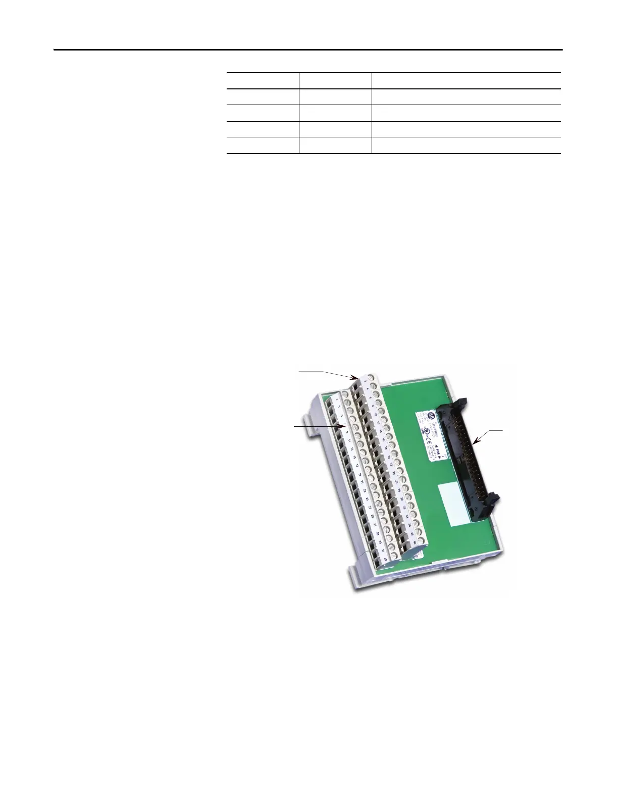
Interface Module (IFM)
The Interface Module is used to make all customer useable connections to the
ACB. The pin numbers listed on the following pages refer to IFM pin numbers.
Figure 294 - Interface Module (IFM)
Analog Inputs and Outputs
The PowerFlex 7000 “C” Frame offers one isolated process current loop
transmitter and three isolated process current loop receivers, embedded into the
control. These are accessible on the ACB.
TP80 BPIS Bypass Isolating Switch
TP81 BPCS Bypass Contactor Status
TP82 BP Bypass Contactor Command
TP83 DGND Digital Ground Return
Test points Name Description
Even pin numbers
Odd pin numbers
Connection to ACB (

 Loading...


