42 Rockwell Automation Publication 7000L-UM301F-EN-P - March 2020
Chapter 2 Drive Installation
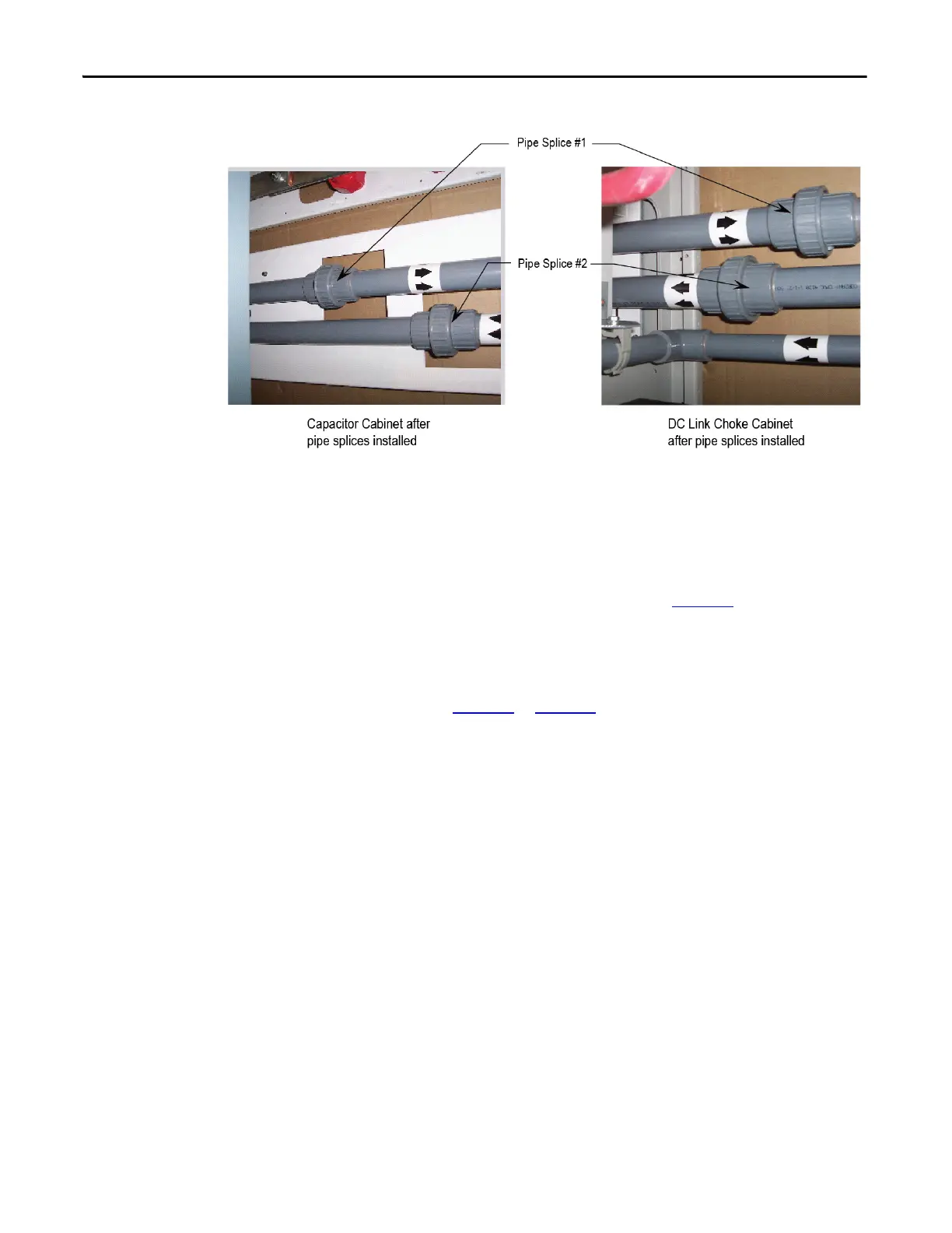
Figure 19 - Capacitor Cabinet and DC Link Choke Cabinet after Pipe Splices installed
Connect Power: M+, L+, M-, L- Power Bus
• Locate the four (4) Power Bus pieces of the splice kit in DC Link Choke
cabinet and remove shipping wrapping. See Figure 20
.
• Connect Power Bus M+, L+, M-, L- on the red insulators in the DC Link
Choke cabinet and mating bus pieces in the capacitor cabinet. Hardware
required is pre-attached to bus connections, cabling, and insulators in the
cabinet where the power bus splice kit will attach. Remove and attach as
shown in Figure 20
to Figure 24.
• Torque M10 carriage bolts connecting bus to bus in the capacitor cabinet
to 29 Nm (21 ft-lb). Torque M12 hardware supplied for cable to bus stab
connections to 50 Nm (37 ft-lb).
• After cable connections have been made, ensure cable connections to
choke stabs are torqued to 50 Nm (37 ft-lb).
• Ensure a minimum of 3" (75mm) clearance exists between Medium
Voltage Bus field connections (including hardware) and all cabinet
sidesheets.
Install according to flow direction labels as shown.

 Loading...


