360 Rockwell Automation Publication 7000L-UM301F-EN-P - March 2020
Chapter 5 Component Definition and Maintenance
ohm input impedance. Regardless of input configuration, each input is
individually isolated to ± 100V DC or 70V RMS AC.
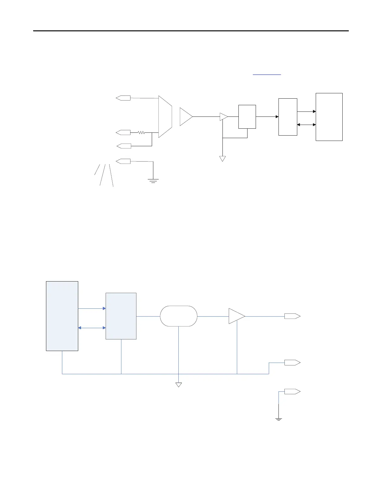
A block diagram of the receiver is shown in Figure 296
.
Figure 296 - Process Loop Receiver Block Diagram
Non-Isolated Process Outputs
The drive supplies four non-isolated -10/0/+10 V outputs for customer use.
These outputs can drive loads with impedances as low as 600 ohms. These
outputs are all referenced to the Drive AGND and therefore should be isolated if
they are required to drive outside the PowerFlex “C” frame enclosure.
Figure 297 - Non-Isolated Configurable Analog Outputs on ACB
4,8,12
3,7,11
ŀ/#
X1 U1
FPGA
DSP
st
I/P pins
3
rd
I/P pins
2
nd
I/P pins
A/D
Buffer
1,5,9
2,6,10
Isolation Amplifier
+
A/D
DSP
FPGA
27,31,35,39
Analog
Output
25,29,33,3

 Loading...


