IFX Parameters
91
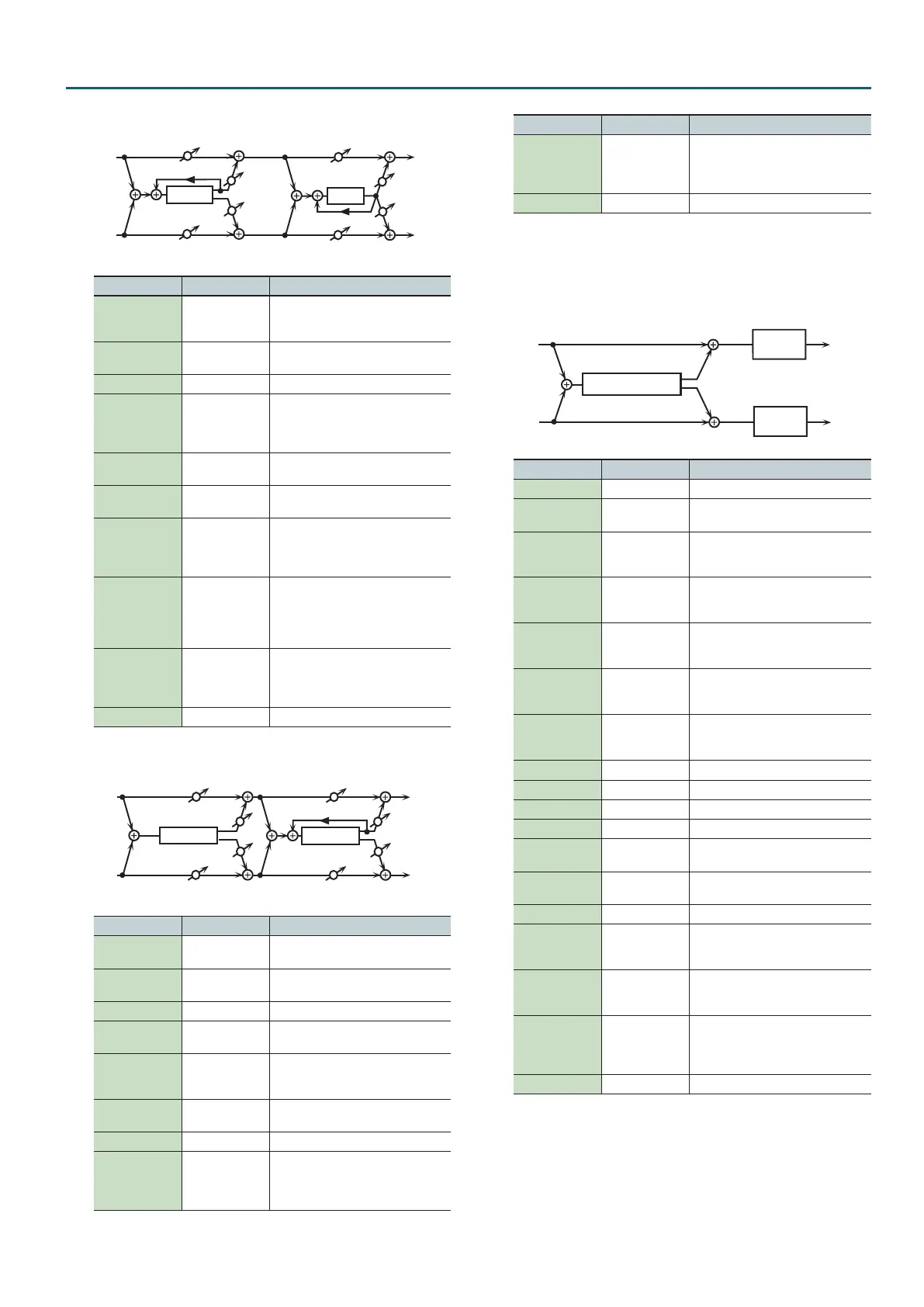
76: Flanger g Delay
Feedback
Delay
L in
R in
L out
R out
Balance W
Balance W
Balance D
Balance D
Flanger
Balance W
Balance W
Balance D
Feedback
Parameter Value Explanation
Flanger Pre
Delay
0.0–100 msec
Adjusts the delay time from when the
direct sound begins until the anger
sound is heard.
Flanger Rate
0.05–10.00 Hz,
note
Frequency of modulation
Flanger Depth 0–127 Depth of modulation
Flanger
Feedback
-98–+98 %
Adjusts the proportion of the anger
sound that is fed back into the eect.
Negative (-) settings will invert the
phase.
Flanger Balance
D100:0W–
D0:100W
Volume balance between the direct
sound (D) and the anger sound (W)
Delay Time
0–2600 msec,
note
Adjusts the delay time from the direct
sound until the delay sound is heard.
Delay Feedback -98–+98 %
Adjusts the proportion of the delay
sound that is fed back into the eect.
Negative (-) settings will invert the
phase.
Delay HF Damp
200–8000 Hz,
BYPASS
Adjusts the frequency above which
sound fed back to the eect will be
cut. If you do not want to cut the high
frequencies, set this parameter to
BYPASS.
Delay Balance
D100:0W–
D0:100W
Adjusts the volume balance between
the sound that is sent through the
delay (W) and the sound that is not
sent through the delay (D).
Level 0–127 Output Level
77: Chorus g Flanger
Feedback
Flanger
L in
R in
L out
R out
Balance W
Balance W
Balance D
Chorus
Balance W
Balance W
Balance D
Parameter Value Explanation
Chorus Pre Delay 0.0–100 msec
Adjusts the delay time from the direct
sound until the chorus sound is heard.
Chorus Rate
0.05–10.00 Hz,
note
Modulation frequency of the chorus
eect
Chorus Depth 0–127 Modulation depth of the chorus eect
Chorus Balance
D100:0W–
D0:100W
Volume balance between the direct
sound (D) and the chorus sound (W)
Flanger Pre
Delay
0.0–100 msec
Adjusts the delay time from when the
direct sound begins until the anger
sound is heard.
Flanger Rate
0.05–10.00 Hz,
note
Modulation frequency of the anger
eect
Flanger Depth 0–127 Modulation depth of the anger eect
Flanger
Feedback
-98–+98 %
Adjusts the proportion of the anger
sound that is fed back into the eect.
Negative (-) settings will invert the
phase.
Parameter Value Explanation
Flanger Balance
D100:0W–
D0:100W
Adjusts the volume balance between
the sound that is sent through the
anger (W) and the sound that is not
sent through the anger (D).
Level 0–127 Output Level
78: Sympathetic Resonance
On an acoustic piano, holding down the damper pedal allows other
strings to resonate in sympathy with the notes you play, creating rich
and spacious resonances. This eect simulates these sympathetic
resonances.
L in
R in
L out
R out
Sym. Resonance
3-Band
EQ
3-Band
EQ
Parameter Value Explanation
Depth 0–127 Depth of the eect
Damper 0–127
Depth to which the damper pedal is
pressed (controls the resonant sound)
Lid 1–6
This simulates the actual changes in
sound that occur when the lid of a
grand piano is set at dierent heights.
Pre LPF
16–15000 Hz,
BYPASS
Frequency of the lter that cuts the
high-frequency content of the input
sound (BYPASS: no cut)
Pre HPF
BYPASS,
16–15000 Hz
Frequency of the lter that cuts the
low-frequency content of the input
sound (BYPASS: no cut)
HF Damp
16–15000 Hz,
BYPASS
Frequency at which the high-
frequency content of the resonant
sound will be cut (BYPASS: no cut)
LF Damp
BYPASS,
16–15000 Hz
Frequency at which the low-frequency
content of the resonant sound will be
cut (BYPASS: no cut)
EQ Low Freq 200, 400 Hz Frequency of the low-range EQ
EQ Low Gain -15–+15 dB Amount of low-range boost/cut
EQ Mid Freq 200–8000 Hz Frequency of the midrange EQ
EQ Mid Gain -15–+15 dB Amount of midrange boost/cut
EQ Mid Q
0.5, 1.0, 2.0, 4.0,
8.0
Width of midrange (larger values
make the region narrower)
EQ High Freq
2000, 4000, 8000
Hz
Frequency of the high-range EQ
EQ High Gain -15–+15 dB Amount of high-range boost/cut
Peaking Freq 200–8000 Hz
Frequency of the lter that boosts/
cuts a specic frequency region of the
input sound
Peaking Gain -15–+15 dB
Amount of boost/cut produced by the
lter at the specied frequency region
of the input sound
Peaking Q
0.5, 1.0, 2.0, 4.0,
8.0
Width of the frequency region
boosted/cut by the Peaking Gain
parameter (larger values make the
region narrower)
Level 0–127 Output Level
 Loading...