5-35
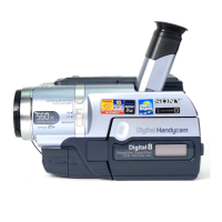
Holizontal line
Specified value : The image should be within
±
1.5
°
of the holizontal line.
θ
θ
±
1.5
°
±
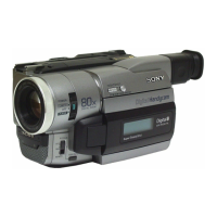
4%
±
4%
Adjustment value :
±
4%
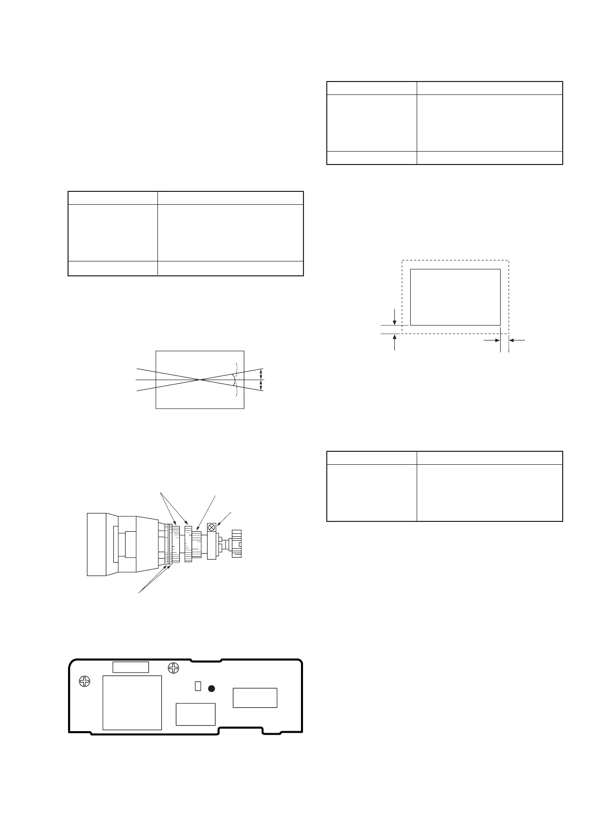
Focus adjustment
Aberration adjustment
DY tightening screw
Centering adjustment
RV903
C909
CN902
IC901
F.B.T
W901
RV904
SOL901
Fig. 5-1-18.
Fig. 5-1-19.
Fig. 5-1-20.
VF-129 BOARD
1-5. MONOCHROME ELECTRONIC
VIEWFINEDER SYSTEM ADJUSTMENTS
DCR-TRV103/TRV110/TRV110E/TRV110P/
TRV203/TRV210/TRV210E/TRV310/
TRV310E/TRV310P
Note: NTSC model: DCR-TRV103/TRV110/TRV110P/TRV203/TRV210/
TRV310/TRV310P
PAL model: DCR-TRV110E/TRV210E/TRV310E
1-5-1. Horizontal Slant Check
Mode Playback
Signal Hi8/standard 8mm alignment tape :
For checking operation
(WR5-8NSE(NTSC))
(WR5-8CSE(PAL))
Monoscope section
Specified Value ± 1.5°
Adjustment method:
1) Adjust RV904 (BRIGHT) (VF-129 board) so that the CRT can
be seen easily and clearly.
2) Check that the difference between the horizontal line and the
tilt of black mask satisfies the specified value.
1-5-2. Centering Adjustment
Mode Playback
Signal Hi8/standard 8mm alignment tape :
For checking operation
(WR5-8NSE(NTSC))
(WR5-8CSE(PAL))
Monoscope section
Specified Value ± 4%
Adjustment method:
1) Use the centering adjustment ring and adjust so that the left,
light, top, and bottom sides of the display are uniform. (Refer
to Fig. 5-1-19.)
Note: As the centering position changes due to earth magnetism,
rotate it 360° in the horizontal direction, and adjust with the
center section of the modifying position.
1-5-3. Focus Adjustment
Mode Playback
Signal Hi8/standard 8mm alignment tape :
For checking operation
(WR5-8NSE(NTSC))
(WR5-8CSE(PAL))
Monoscope section
Adjustment method:
1) Adjust the focus ring to obtain the optimum focus. (Refer to
Fig. 5-1-19.)
(
)
 Loading...