DCR-TRV103/TRV110/TRV110E/TRV110P/TRV203/TRV210/
TRV210E/TRV310/TRV310E/TRV310P/TRV315
DCR-TR7000/TR7000E/TR7100E
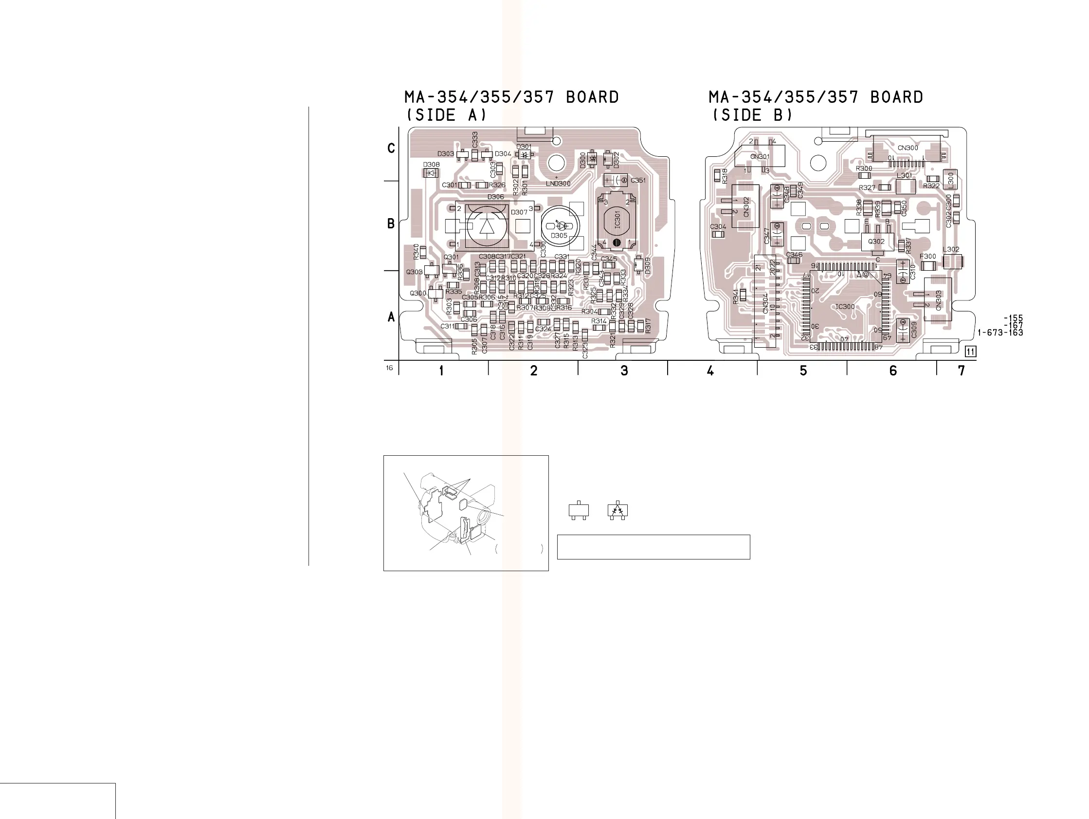
MA-354/355/357 BOARD
MA-354/355/357 (STEREO MIC AMP) PRINTED WIRING BOARD
— Ref. No. MA-354 Board; 7,000, MA-355 Board; 8,000, MA-357 Board; 9,000 Series —
For printed wiring boards
• Chip parts
Transistor Diode
There are few cases that the part printed on this
diagram isn’t mounted in this model.
4-75 4-76
STEREO MIC AMP
MA-354/355/357
CD-212, 213
(CCD IMAGER)
MA-354, 355, 357
STEREO MIC AMP,
LASER LINK
PJ-95, 96, 98
(AV IN/OUT)
SE-86, 87, 89
(STEADY SHOT)
DD-117
(DC/DC CONVERTER)
VF-126
(COLOR EVF)
C
BE
3
21
C300 B-7
C301 B-1
C302 B-7
C303 C-2
C304 B-4
C305 A-1
C306 A-1
C307 A-1
C308 B-2
C309 A-6
C310 A-6
C311 A-1
C312 A-2
C313 B-1
C314 A-2
C315 A-2
C316 A-2
C317 B-2
C318 A-2
C319 A-2
C320 B-2
C321 B-2
C322 A-2
C323 A-3
C324 A-2
C325 A-2
C326 B-2
C327 A-2
C328 A-3
C329 A-3
C330 B-2
C331 B-2
C332 A-2
C333 C-1
C343 A-3
C344 B-3
C345 B-3
C346 B-5
C347 B-5
C348 B-5
C349 B-5
C350 B-6
C351 C-3
CN300 C-6
CN301 C-4
CN302 B-4
CN303 A-7
CN304 A-5
D301 C-2
D302 C-3
D303 C-1
D304 C-1
D305 B-2
D306 B-1
D307 B-2
D308 C-1
D309 B-3
F300 B-6
IC300 A-5
IC301 B-3
L300 C-7
L301 B-6
L302 B-7
Q300 A-1
Q301 B-1
Q302 B-6
Q303 B-1
R300 C-6
R301 C-2
R302 C-2
R303 A-1
R304 A-3
R305 A-1
R306 A-1
R307 A-2
R308 A-1
R309 A-2
R310 A-2
R311 A-2
R312 A-2
R313 A-2
R314 A-3
R315 A-2
R316 A-2
R317 A-3
R318 C-4
R319 A-2
R320 B-2
R321 A-3
R323 A-2
R324 B-2
R325 A-3
R326 B-1
R327 B-6
R331 B-3
R332 A-3
R333 A-3
R334 A-3
R335 A-1
R336 A-1
R337 B-6
R338 B-6
R339 B-6
R340 B-1
R341 A-4
Note : This series use the three different types of printed wiring board as shown below.
DCR-TRV103/TRV110/TRV110E/TRV110P : MA-354 : 1-673-155-
DCR-TRV203/TRV210/TRV210E/TRV310/TRV310E/TRV310P/TRV315 : MA-355 : 1-673-167-
DCR-TR7000/TR7000E/TR7100E : MA-357 : 1-673-163-
 Loading...