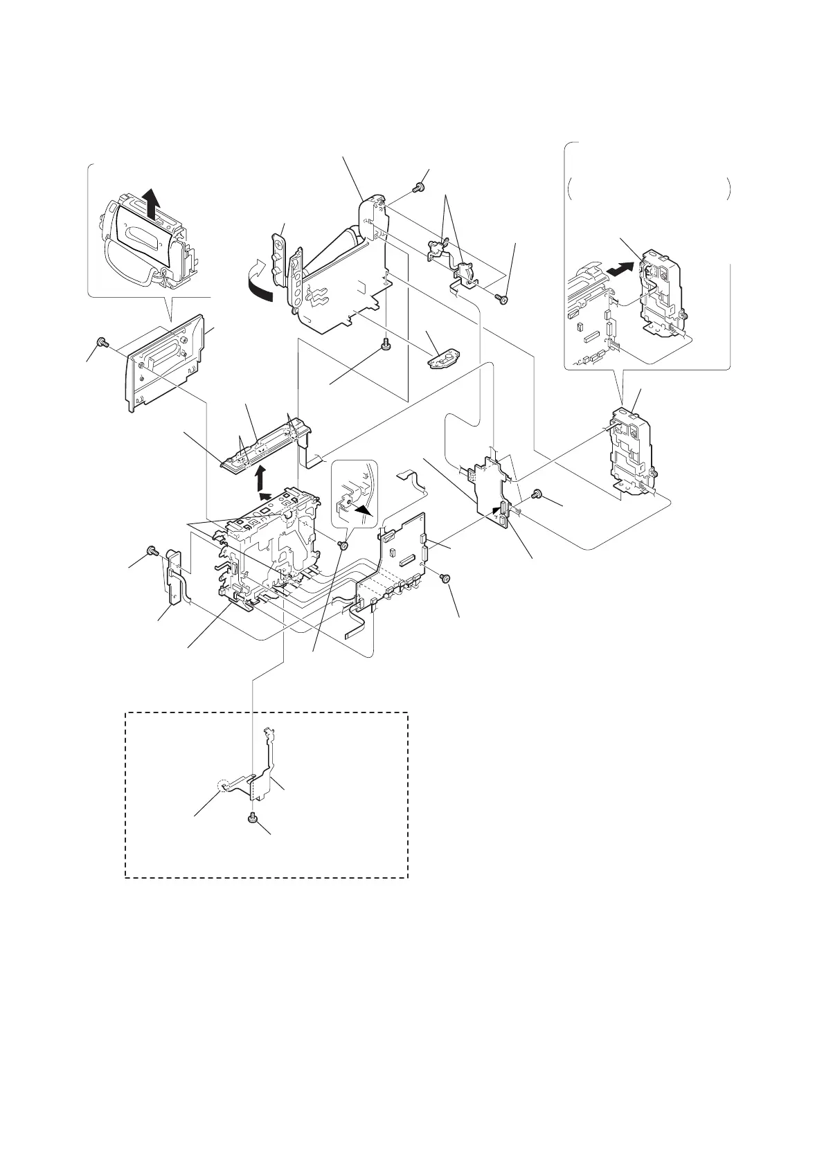
2-10
VC-213
Board
DD-117
3
Screw (M2
×
4),
lock ace, p2
4
Screw
(M2
×
4),
lock ace,
p2
5
Battery panel
(P) assembly
1
Two screws
(M2
×
3),
lock ace, p2
2
Cassette
Lid
assembly
b
a
!ª
Remove
the claw
e
e
7
Jack cover
8
Screw
!º
Two tapping
screws (B2
×
5)
!¡
Control switch block
(SS-8500)
!§
Two screws
(M2
×
3)
!¶
Board to board connector (70P)
!•
DD-117
board
@¡
Two screws
(M2
×
4),
lock ace, p2
@™
PJ-95, 96, 98 board
@£
Screw
(M2
×
3)
!£
Screw
(M2
×
3)
!∞
IM shield assembly
!¢
Claw
@¢
Remove the claws
@∞
VC-213
board
9
Screw
(M2
×
3)
@§
Mechanism
deck
6
Disengage the claw
that fixes the flexible board.
@º
Slide it in the direction
of the arrow
c
and
disengage the claw
e
.
Remove the control switch
block(FK-8500) in the
direction of the arrow
d
.
Remove it in the direction
of the arrow
a
.
Remove it gently as a thin
flexible board is held by a claw.
Remove it in the direction of the arrow
b
.
d
c
!™
Cabinet (R) assembly
PAL MODELS ONLY
2-10.MECHANISM DECK, VC-213, DD-117, PJ-95, 96, 98 BOARDS
 Loading...