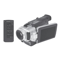
VC-213
Tilt lock (93)
1
Screw
2
Slide the button in the
direction of the arrow
a
.
a
b
c
AC POWER
ADAPTOR
FP-77 flexible board (22P)
Cabinet (R) assembly
AC IN
LANC jack
DC IN
Adjustment remote
commander (RM-95)
CPC-13 jig
(J-6082-443-A)
CPC-13 jig
@¡
CRT socket (4P)
@¢
CRT
@£
Anode cable (1P)
Do not pull the cable,
but remove it in the vertical
direction.
@™
Remove the connector
cover with a flat head (–)
screwdriver.
@º
CRT DT connector (4P)
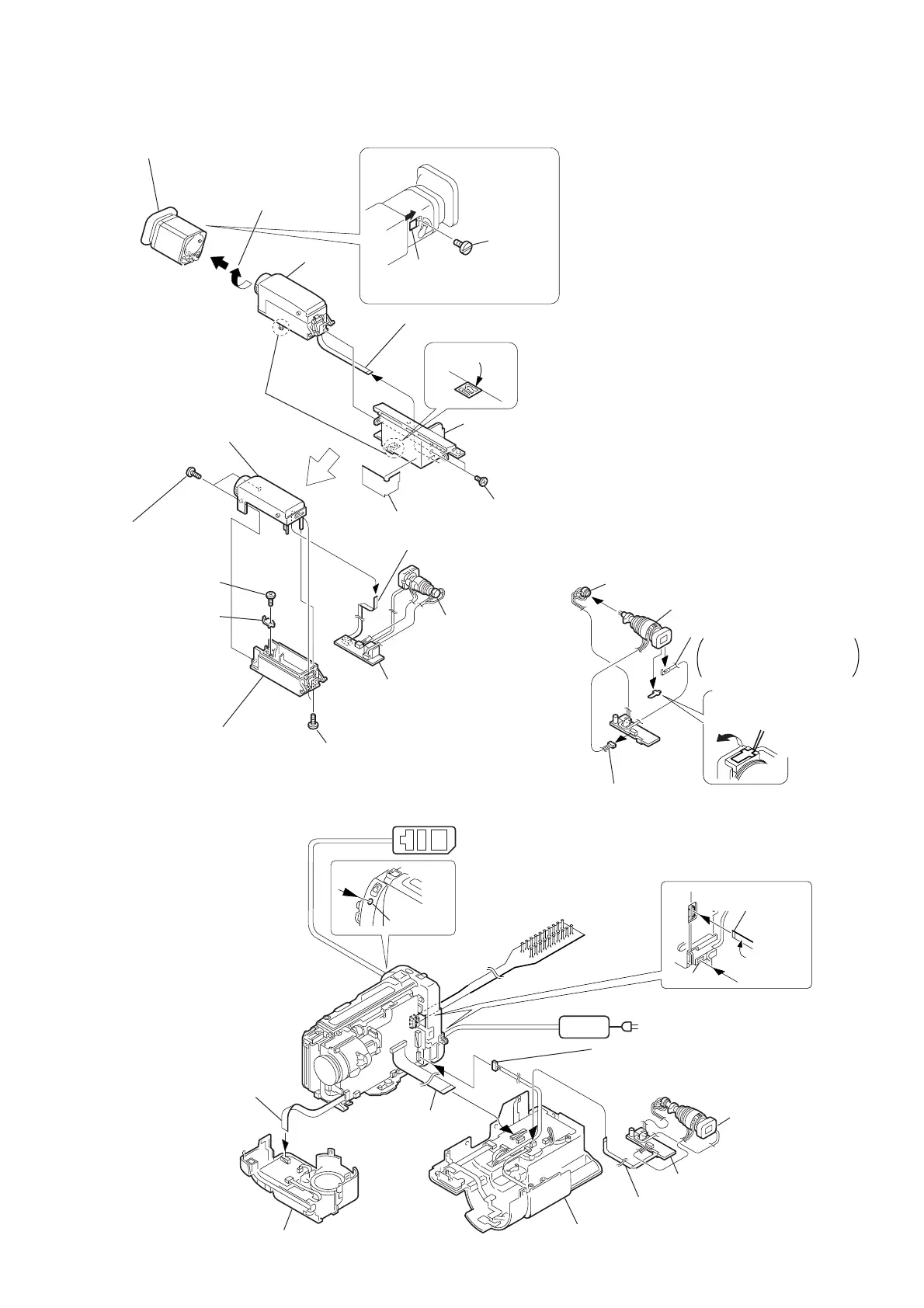
[How to remove the CRT unit]
FFC-236 flexible
flat cable (50P)
DP-74 harness (10P) (2.5 INCH LCD MODEL)
DP-75 harness (10P) (3.0/3.5 INCH LCD MODEL)
4
Finder (S) assembly
!™
Two tapping
screws (B2
×
5)
!§
Tapping
screw (B2
×
5)
!¶
EVF tally
!∞
EVF cabinet (upper B) (95)
assembly
!¢
EVF cabinet (lower B) (95)
!¡
Tapping screw (B2
×
5)
8
FFC-256
flexible flat cable (4P)
!£
FFC-256
flexible flat cable (4P)
FFC-256 flexible flat cable (4P)
9
VF base(B)(95)
!º
3
Rotate it in the direction of
the arrow
b
and remove it
in the direction of the arrow
c
.
7
Remove
the claw
6
Two screws
(M2
×
3)
5
Harness guide
!ª
CRT assembly
CRT assembly
!•
VF-129 board
VF-129 board
[B/W EVF CHECK SERVICE POSITION]
Panel (N) (front) assembly
Note: the TR models do not have the harness
(DP-74 or DP-75)
Insulater
side
2-7. VF-129 BOARD (B/W EVF MODEL)
 Loading...