— 3 —
SAFETY-RELATED COMPONENT WARNING!!
COMPONENTS IDENTIFIED BY MARK ! OR DOTTED LINE WITH
MARK ! ON THE SCHEMATIC DIAGRAMS AND IN THE PARTS
LIST ARE CRITICAL TO SAFE OPERATION. REPLACE THESE
COMPONENTS WITH SONY PARTS WHOSE PART NUMBERS
APPEAR AS SHOWN IN THIS MANUAL OR IN SUPPLEMENTS
PUBLISHED BY SONY.
ATTENTION AU COMPOSANT AYANT RAPPORT
À LA SÉCURITÉ!
LES COMPOSANTS IDENTIFÉS PAR UNE MARQUE ! SUR LES
DIAGRAMMES SCHÉMATIQUES ET LA LISTE DES PIÈCES SONT
CRITIQUES POUR LA SÉCURITÉ DE FONCTIONNEMENT. NE
REMPLACER CES COMPOSANTS QUE PAR DES PIÈSES SONY
DONT LES NUMÉROS SONT DONNÉS DANS CE MANUEL OU
DANS LES SUPPÉMENTS PUBLIÉS PAR SONY.
1. Check the area of your repair for unsoldered or poorly-soldered
connections. Check the entire board surface for solder splashes
and bridges.
2. Check the interboard wiring to ensure that no wires are
"pinched" or contact high-wattage resistors.
3. Look for unauthorized replacement parts, particularly
transistors, that were installed during a previous repair. Point
them out to the customer and recommend their replacement.
4. Look for parts which, through functioning, show obvious signs
of deterioration. Point them out to the customer and
recommend their replacement.
5. Check the B+ voltage to see it is at the values specified.
6. Flexible Circuit Board Repairing
• Keep the temperature of the soldering iron around 270˚C
during repairing.
• Do not touch the soldering iron on the same conductor of the
circuit board (within 3 times).
• Be careful not to apply force on the conductor when soldering
or unsoldering.
SAFETY CHECK-OUT
After correcting the original service problem, perform the following
safety checks before releasing the set to the customer.
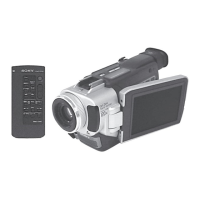
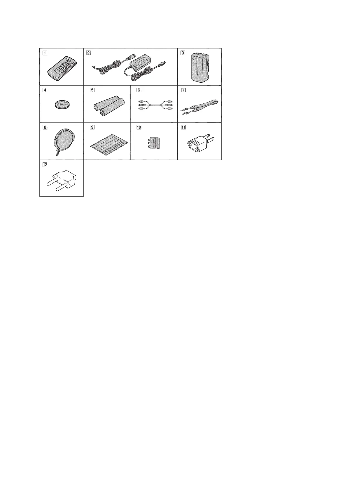
Supplied accessories
1 Wireless Remote Commander (1)
2 AC-L10A/L10B/L10C AC power
adaptor (1), Power cord (1)
3 NP-F330 Battery pack (1)
4 CR2025 Lithium Battery (1)
The lithium battery is already installed in your
camcorder.
5 Size AA (R6) battery for Remote
Commander (2)
6 A/V connecting cable (1)
!™ 2-pin conversion adaptor (1)
DCR-TRV110E: JE/TRV310E: JE/
TRV310: JE only
• Abbreviation
EE :
East European model
NE :
North European model
RU : Russian model
HK : Hong Kong model
BR : Brazilian model
JE : Tourist model
7 Shoulder strap (1)
8 Lens cap (1)
9 Label sheet for cassette (1)
Stick this label on the recorded cassette.
0 21-pin adaptor (1)
DCR-TR7000E/TR7100E/TRV210E: AEP, UK/
TRV310E: AEP, UK/TRV110E: AEP, UK,
EE, NE, RU only
!¡ 2-pin conversion adaptor (1)
DCR-TRV110E: E, HK/TRV110: E, HK, BR/
TRV110P/TRV310E: E, HK/TRV310: E, HK/
TRV310P only
 Loading...