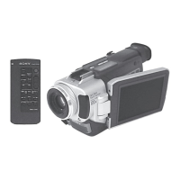
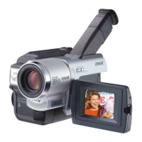
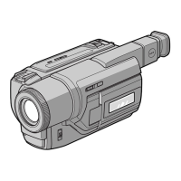
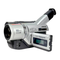
DCR-TRV103/TRV110/TRV110E/TRV110P/TRV203/TRV210/
TRV210E/TRV310/TRV310E/TRV310P/TRV315
DCR-TR7000/TR7000E/TR7100E
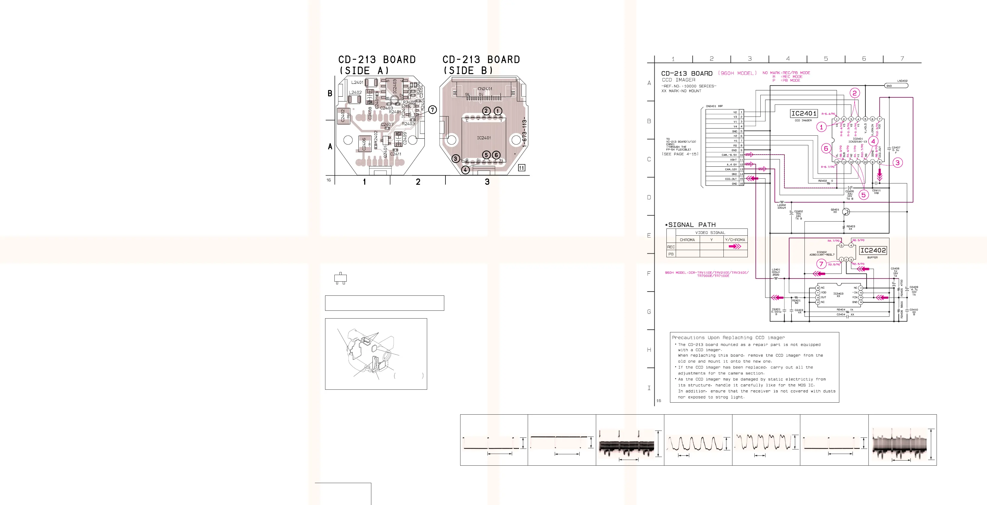
CD-213 (CCD IMAGER) PRINTED WIRING BOARD (960H MODEL)
— Ref. No. CD-213 Board; 10,000 Series —
4-13 4-14
CCD IMAGER
CD-213
CD-213 BOARD
For printed wiring boards
• This board is eight-layer print board. However, the pat-
terns of layers two to seven have not been included in
the diagram.
• Chip parts
Transistor
There are few cases that the part printed on this
diagram isn’t mounted in this model.
C
BE
CD-212, 213
(CCD IMAGER)
MA-354, 355, 357
STEREO MIC AMP,
LASER LINK
PJ-95, 96, 98
(AV IN/OUT)
SE-86, 87, 89
(STEADY SHOT)
DD-117
(DC/DC CONVERTER)
VF-126
(COLOR EVF)
C2401 B-1
C2402 A-1
C2403 B-1
C2404 B-2
C2406 A-1
C2407 A-1
C2408 B-1
C2409 A-2
C2410 B-2
C2411 A-2
CN2401 B-3
IC2401 A-3
IC2402 B-2
IC2403 B-2
L2401 B-1
L2402 B-1
Q2401 A-1
R2401 B-2
R2402 A-1
R2403 B-2
R2404 B-2
R2405 B-2
R2406 B-2
CD-213
BOARD
CAMERA REC
2 IC2401 3,4
3 IC2401 8
4 IC2401 !º
0.9Vp-p
H
3.0Vp-p
56 nsec
56 nsec
5 IC2401 !¡,!™
3.0Vp-p
H
1.0Vp-p
7 IC2402 1
1 IC2401 1,2
6.5Vp-p
H
6 IC2401 !£
18Vp-p
H
6.5Vp-p
H
DCR-TRV103/TRV110/TRV110E/TRV110P/TRV203/TRV210/
TRV210E/TRV310/TRV310E/TRV310P/TRV315
DCR-TR7000/TR7000E/TR7100E
 Loading...