2-4
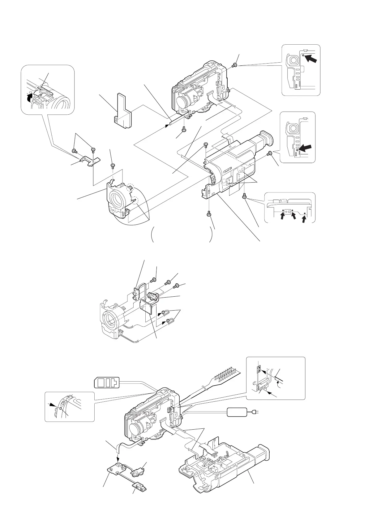
VC-213
VC-213
1
Two screws (M2
×
4),
lock ace, p2
2
Remove
the claw
4
Screw
(M2
×
4),
lock ace, p2
3
Cabinet (S) shoe
5
Screw
(M2
×
4),
lock ace, p2
!™
Screw (M2
×
4),
lock ace, p2
!£
Screw (M2
×
4),
lock ace, p2
Note
!¢
Two screws (M2
×
4),
lock ace, p2
8
FP-77 flexible board (22P)
6
Screw (M2
×
4),
lock ace, p2
9
Panel (N) (front)
assembly
!º
Cushion (N)
Note
!¡
Three screws (M2
×
4),
lock ace, p2
7
Remove the claws
Remove it while taking
care as the FP-77 flexible
cable is connected.
!∞
Remove the
claws
!§
Cabinet (R) assembly
2
FP-76 flexible board (8P)
1
Two tapping screws (B2
×
5)
3
Two tapping screws
(B2
×
5)
4
Control switch block
(MF-9500) (4P)
5
Two harnesses
(from microphone)
7
MA-354, 355, 357 board
6
Tapping screw
(B2
×
5)
AC POWER
ADAPTOR
FP-77 flexible board (22P)
Cabinet (R) assembly
AC IN
LANC jack
DC IN
Adjustment remote
commander (RM-95)
CPC-13 jig
(J-6082-443-A)
CPC-13 jig
FP-76 flexible board (8P)
Control switch block
(MF-9500) (4P)
MA-354, 355, 357 board
Insulater
side
Note: the TR models do not have
the harness (DP-74 (2.5 INCH LCD MODEL)
or DP-75 (3.0/3.5 INCH LCD MODEL))
shown by Note.
[MA-354, 355, 357 BOARD CHECK SERVICE POSITION]
Note: the TR models do not have the harness
(DP-74 (2.5 INCH LCD MODEL)
or DP-75 (3.0/3.5 INCH LCD MODEL))
shown by Note.
2-3. F PANEL ASSEMBLY, CABINET (R) ASSEMBLY
2-4. MA-354, 355, 357 BOARD
 Loading...