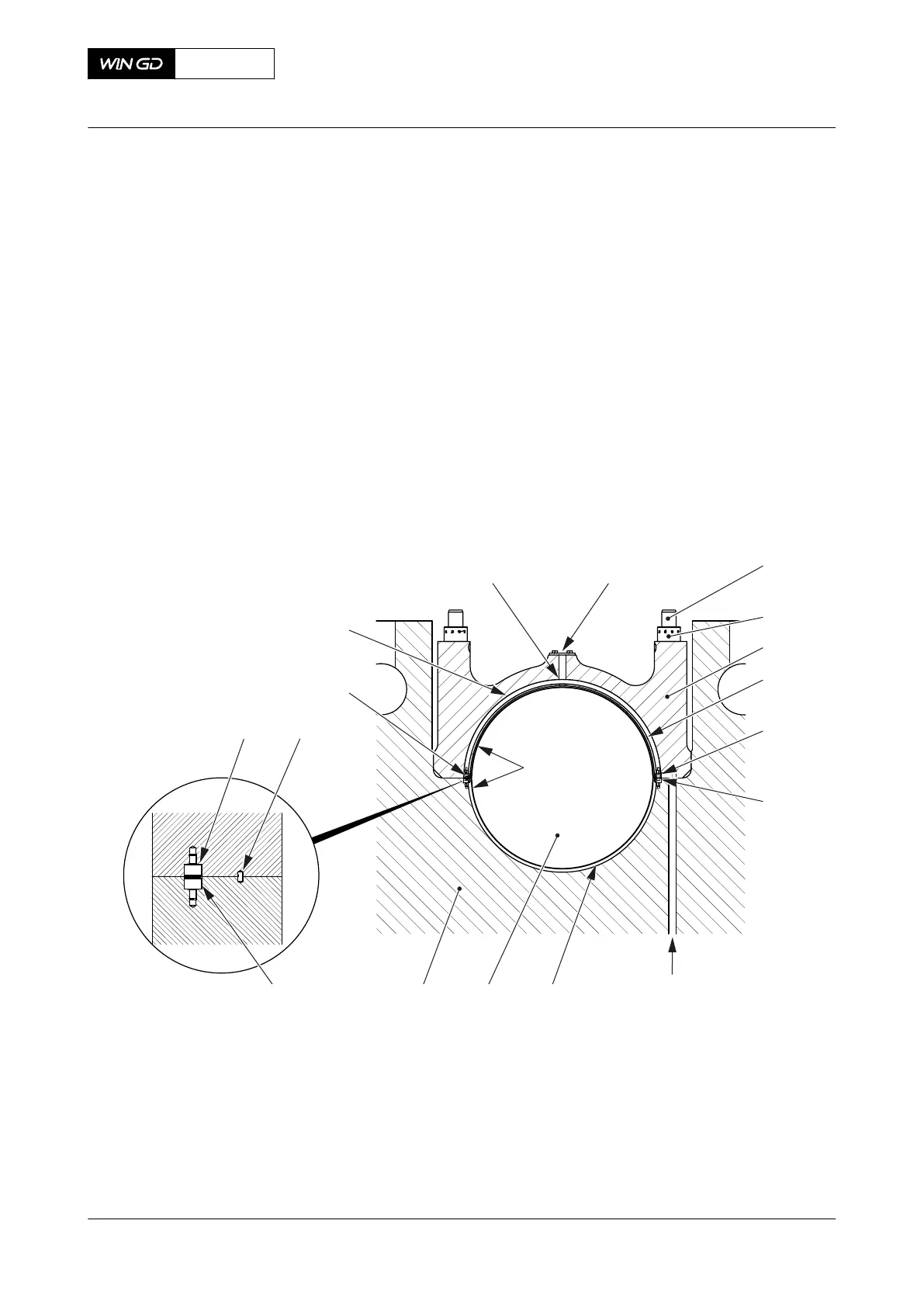
5.1.2 Main bearing
The main bearings hold the crankshaft (007, Figure 5-2) and transmit the forces through the
bearing girders (008) into the bedplate.
The bottom bearing shell (006) is installed in the bearing girder (008) of the bedplate and the
top bearing shell (004) in the bearing cover (003). The screws (005) engage and hold the top
bearing shell and bottom bearing shell in position. The spring dowel pin (009) helps to get the
bearing cover (003) in position.
The elastic studs (001) have a non-hardening locking compound applied to the threads.
Hydraulic tension is applied to the elastic studs during the install procedure. The round nuts
(002) keep the bearing cover (003) against the bearing girder.
For the main bearings adjacent to the thrust bearing the oil flows through the oil bore (013) to
the running surface of the bearing. For the other main bearings the oil flows from the oil supply
pipe through the oil inlet (011) to the running surface of the bearings.
Fig 5-2 Main bearing (generic)
001
002
003
004
005
005
011
006007008
005
005
009
009
012
013
014
010
Legend
001 Elastic stud 008 Bearing girder
002 Round nut 009 Spring dowel pin
003 Bearing cover 010 Flange
004 Top bearing shell 011 Oil inlet
005 Screw 012 Oil groove
006 Bottom bearing shell 013 Oil bore
007 Crankshaft 014 Coating
X92DF
AA00-1132-00AAA-043A-A
Operation Manual Main bearing
Winterthur Gas & Diesel Ltd.
- 150 - Issue 002 2020-08
 Loading...


