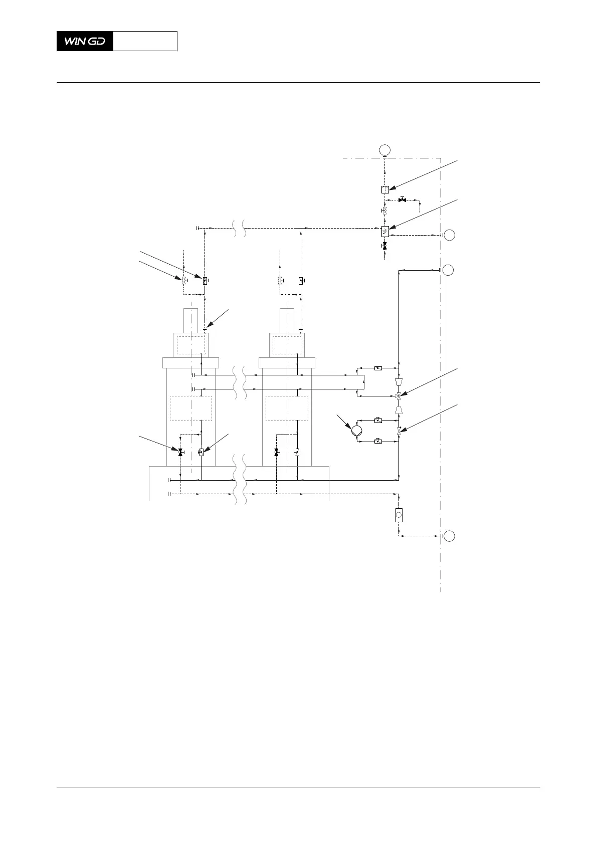
Fig 4-2 Cooling water system (generic and simplified)
Cyl. 1 Cyl. n
ENGINE
PLANT
44
03
02
05
001
002
003
004
005
006
007
008
009
010
Legend
001 Automatic venting unit 006 Orifice
002 Cyclone separator 007 Shut-off valve cooling water inlet
003 Temperature control valve 008 Drain valve (usually closed)
004 Check valve 009 Vent valve (usually closed)
005 Booster pump 010 Shut-off valve cooling water outlet
X92DF
AA00-0000-00AAA-043A-A
Operation Manual Cooling water system
Winterthur Gas & Diesel Ltd.
- 81 - Issue 002 2020-08
 Loading...


