3 Prepare the cooling water system for operation.
3.1 For an engine with a bypass cooling water system (refer to Figure 8-1), and
when the liner wall temperature is between 60°C and 90°C (for example when
the engine is pre-heated or after engine full stop for a sufficient period), release
the unwanted air with a high flow rate as follows:
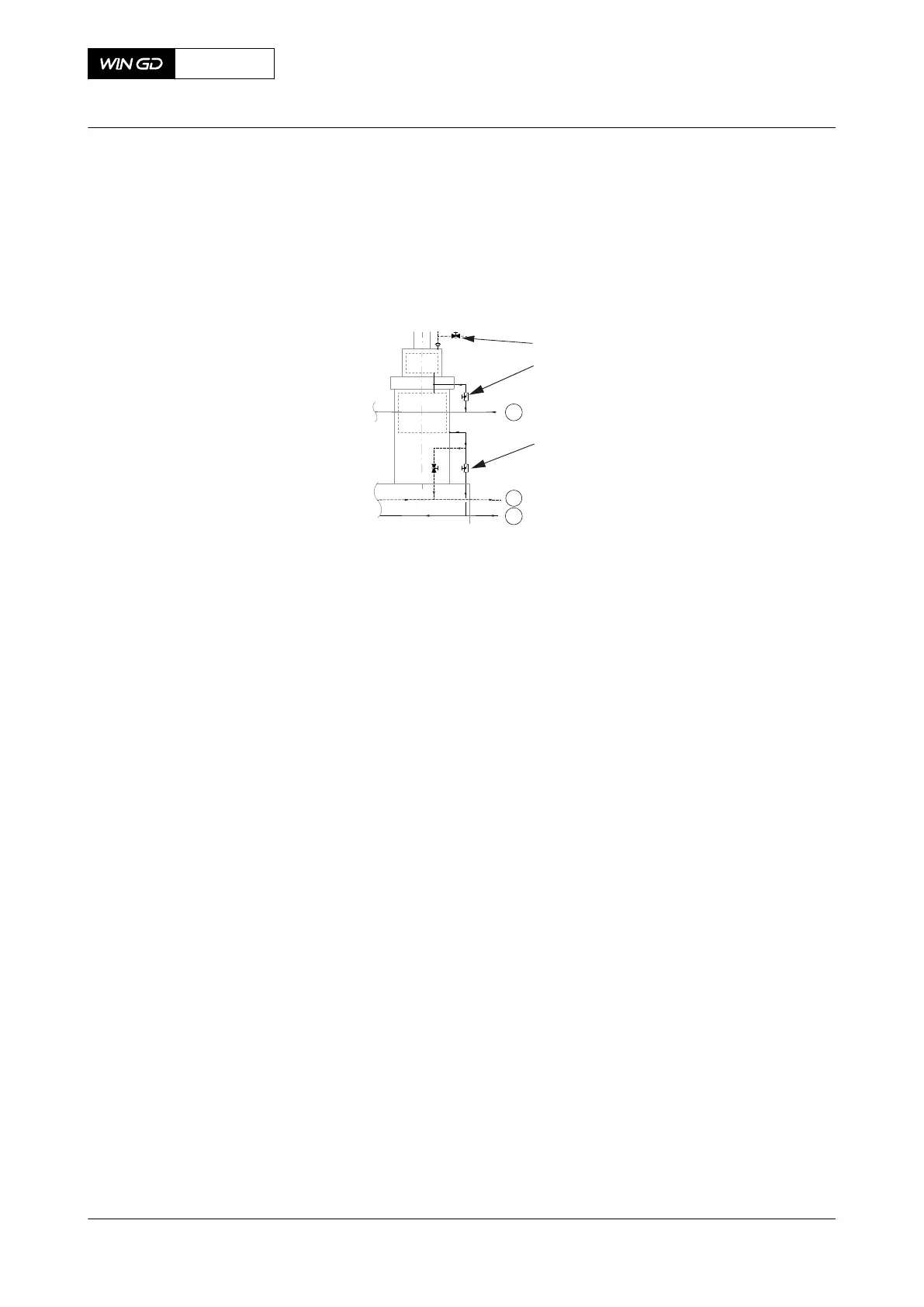
Fig 8-1 Cooling water system with bypass cooling
Legend
001 Optional vent valve 01 Connection 01 (cylinder cooling water inlet)
002 Shut-off valve 02 Connection 02 (cylinder liner CW inlet)
003 Shut-off valve 05 Connection 05 (cylinder CW drain outlet)
3.1.1 Close all shut-off valves (002) in the cylinder cover supply pipes (engine
connection 01).
NOTE: This increases the pressure and thus the flow rate at the
engine connection 02.
3.1.2 Let the cooling water flow through the cylinder liners for approximately
ten minutes.
3.1.3 Close the shut-off valves (003) in the cylinder liner supply pipes of the
first half of cylinders (for example cylinder 1 to 3 for a 5 or 6 cylinder
engine).
NOTE: This increases again the pressure and thus the flow rate to the
other cylinders.
3.1.4 Let the cooling water flow through the other cylinder liners for
approximately ten minutes.
3.1.5 Open the shut-off valves (003) in the cylinder liner supply pipes of the
first half of cylinders.
3.1.6 Do Step 3.1.3 to Step 3.1.5 again for the second half of cylinders (for
example for cylinder 4 and 5 or for cylinder 4 to 6).
3.1.7 Open all shut-off valves (002) in the cylinder cover supply pipes.
3.1.8 If there is unwanted air in the cooling water and the optional vent valve
(001) is installed, do as follows:
3.1.8.1 Put an applicable container under the vent valve (001).
3.1.8.2 Carefully open the vent valve (001) until only cooling water flows
out of the vent valve (001).
3.1.8.3 Close the vent valve (001).
3.1.8.4 Discard the hot cooling water correctly.
X92DF
AA00-0000-00AAA-121A-A
Operation Manual Prepare the engine before start
Winterthur Gas & Diesel Ltd.
- 432 - Issue 002 2020-08
 Loading...


