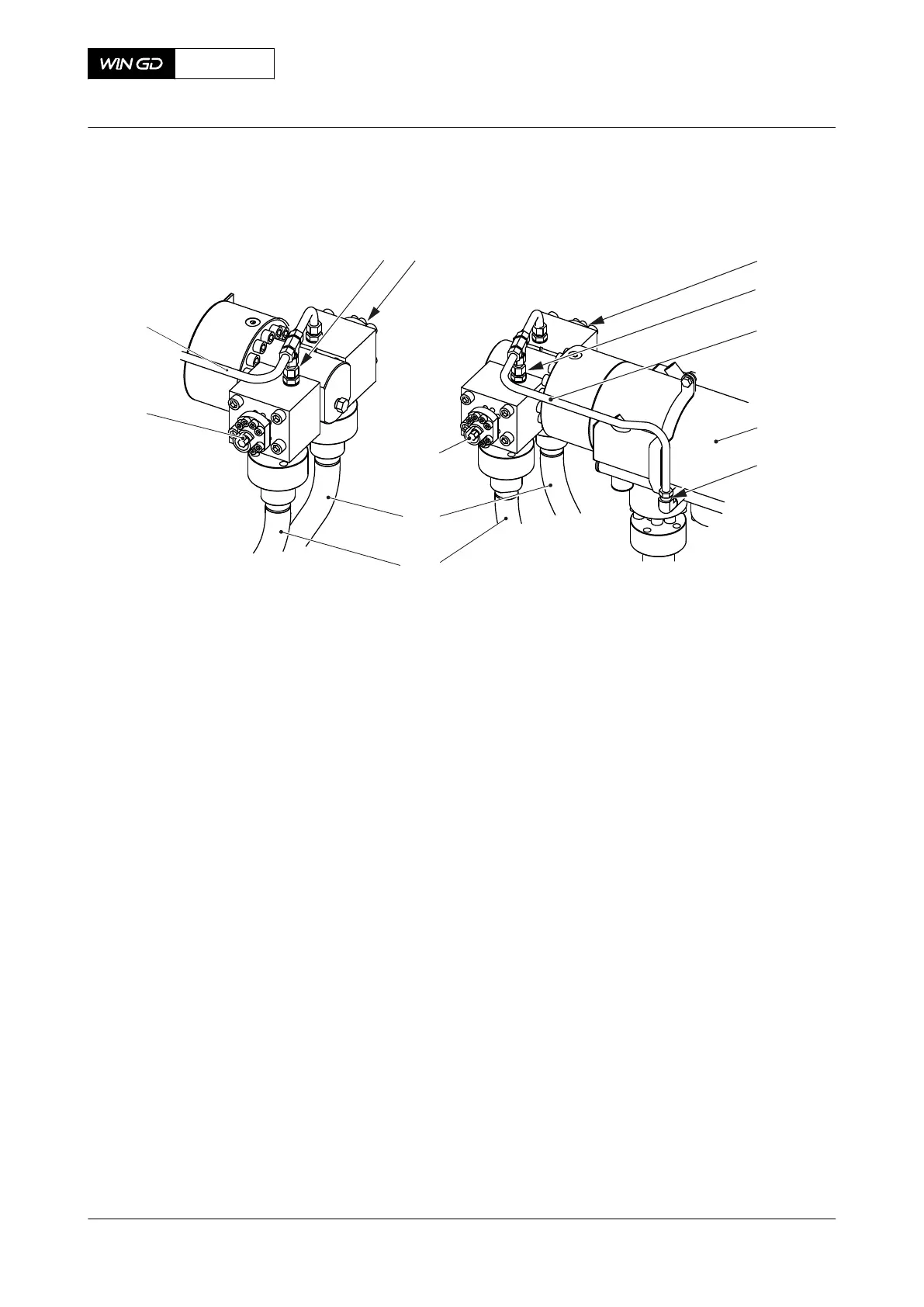
Fig 10-4 Leakage on connecting pipes (generic)
001
002
003
004
005
007
008
006
009
010
011 012
Legend
001 Valve 007 Connecting pipe
002 Screw-in union 008 Valve
003 Leakage pipe 009 Valve
004 Fuel rail 010 Leakage pipe
005 Screw-in union 011 Screw-in union
006 Connecting pipe 012 Valve
5 If none of the connecting pipes have a leakage, find the ICU that has a fuel flow more
than usual (compared to the amount of leakage from the other ICU) as follows:
5.1 Put an oil tray under the screw-in union (008, Figure 10-3) of the fuel leakage
pipe (007) to collect the usual fuel flow.
5.2 Carefully loosen the screw-in union (008) a maximum of two turns.
5.3 Do a check of the fuel flow.
5.4 If fuel flows from the screw-in union (008) more than usual (compared to the
amount of leakage from the other ICU), the fuel quantity piston is defective.
Replace the defective fuel quantity piston (refer to the Maintenance Manual
5564‑1).
5.5 Tighten the screw-in union (008).
5.6 Do Step 5.1 to Step 5.5 again for the other related cylinders.
CLOSE UP
• None
X92DF
AA00-0000-00AAA-311D-A
Operation Manual Examine the ICU or fuel pipes for fuel leakage
Winterthur Gas & Diesel Ltd.
- 545 - Issue 002 2020-08
 Loading...


