PROCEDURE
1 Do a check of the level switch LS3426A (if applicable also LS3427A) for free flow. If
necessary, clean the bore of the pipe of the level switch.
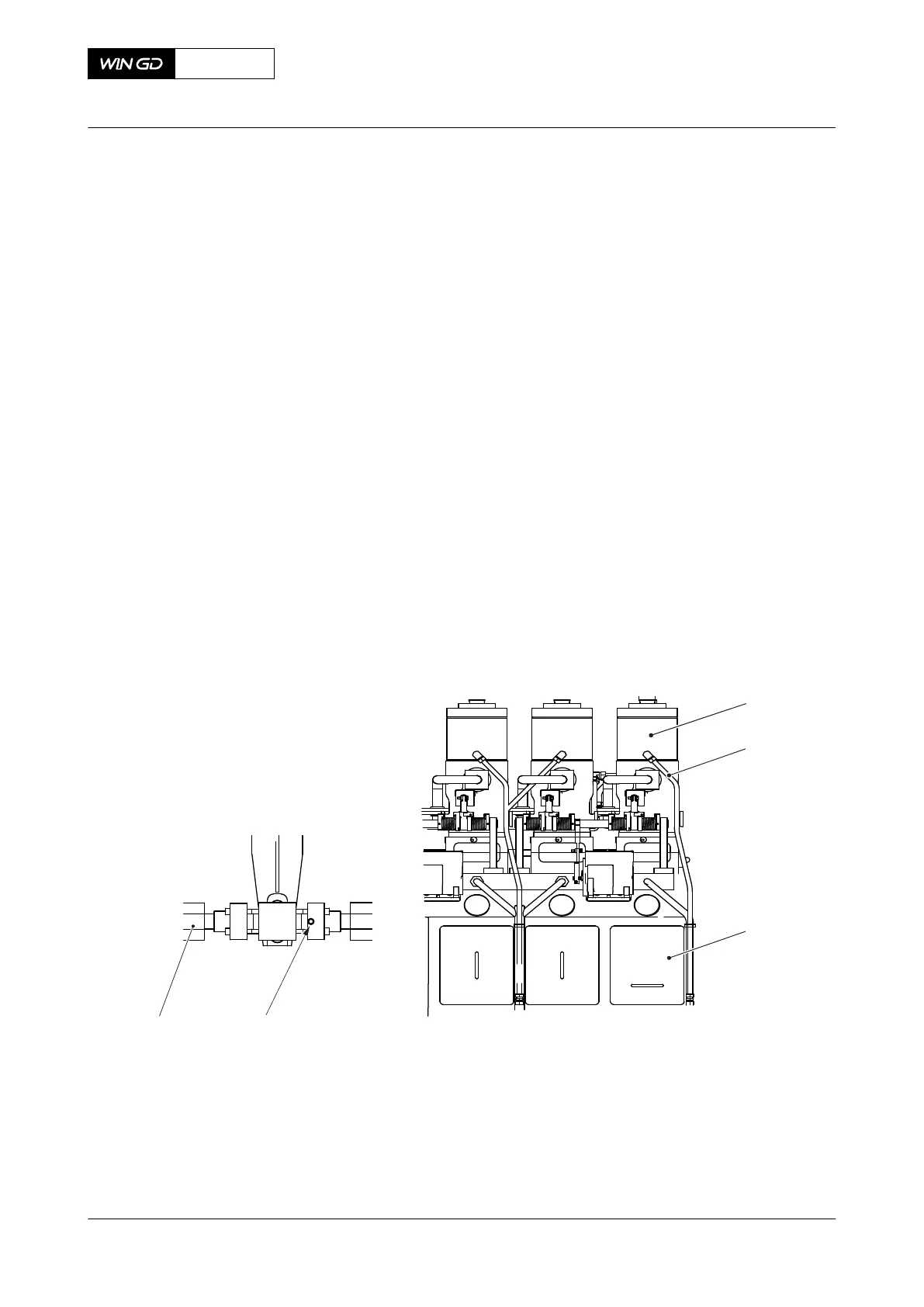
2 Carefully do a check of the temperature of the fuel leakage pipe (002, Figure 10-2) of
each fuel pump (001) to find the leakage pipe that has a fuel flow.
NOTE: There is a fuel flow in the leakage pipe that has a higher temperature than the
other leakage pipes.
3 Continue with Step 4 to find the location of the leakage at the related fuel pump and its
HP fuel pipes.
4 Do a check of the HP fuel pipe (005) at the highest inspection point (004) for leaks.
4.1 Carefully loosen the screw plug a maximum of two turns.
4.2 Do a check for fuel flow.
4.3 If there is fuel flow, repair the cause of the fuel flow as soon as possible, refer to
the Maintenance Manual 8752‑1.
NOTE: The fuel system has high pressure. Replace a defective HP fuel pipe
only when the engine has stopped and the pressure in the system is
released.
4.4 Tighten the screw plug.
Fig 10-2 Supply unit (example) and example of inspection point
Legend
001 Fuel pump 004 Inspection point
002 Fuel leakage pipe 005 HP fuel pipe
003 Supply unit
X92DF
AA00-0000-00AAA-311B-A
Operation Manual Examine the supply unit for fuel leakage
Winterthur Gas & Diesel Ltd.
- 537 - Issue 002 2020-08
 Loading...


