Home
Xerox
All in One Printer
DocuColor 12/DCCS50
Xerox DocuColor 12/DCCS50 User Manual
5
of 1
of 1 rating
1617 pages
Give review
Manual
Specs
To Next Page
To Next Page
To Previous Page
To Previous Page
Loading...
1/05
9-10
DocuColor 12/DCCS50
Edit Pad-to-IOT Mounting Kit Installation
Reissue
Inst
al
lation Instructions
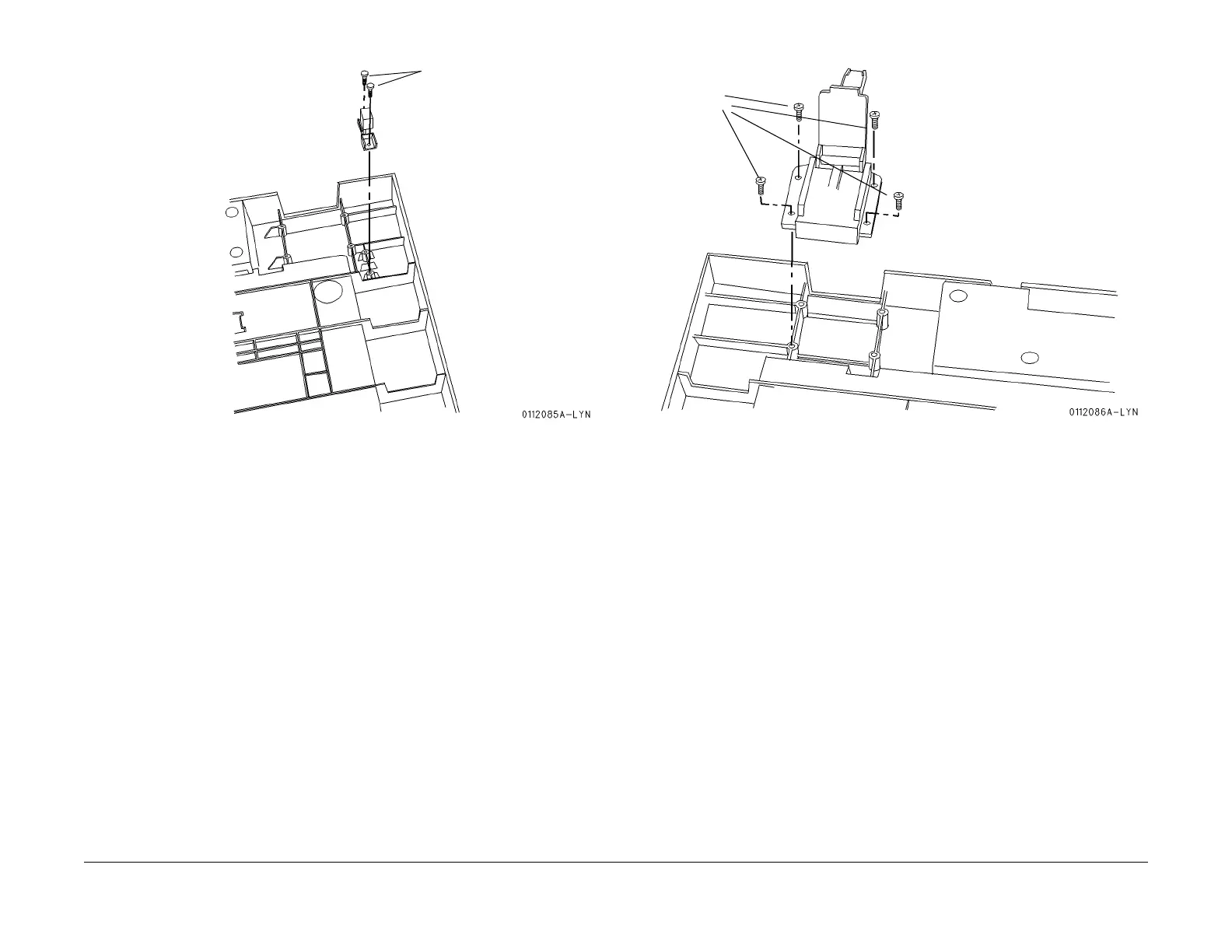
Figure 2 Install the Actuator
4.
Install the Hinges (
Figu
re 3
).
Figure 3 Inst
all the Hinges
5.
Install t
he S
topper (
Figure 4
).
M3 x 10 mm
screws (
2)
M4 x10
mm
scre
ws
(4 each
side)
manuals4you.com
manuals4you.com
1383
1385
Table of Contents
Table of Contents
3
Introduction
3
Safety
5
Laser Hazard Statement
5
Introduction
5
Service Call Procedures
6
About this Documentation
6
Organization
6
Reference Symbology
8
DC Voltage Levels
11
AC and DC Voltage Nomenclature
11
Translated WARNINGS
11
Publication Information
12
Initial Actions
31
Service Strategy
31
Call Flow
32
Call Flow
33
Detailed Maintenance Activities (HFSI)
34
ADC and Jam Sensors
36
Cleaning Procedures
36
Final Actions
36
Toner Dispense Units
36
Status Indicator Raps
37
Front Door Interlock Open RAP
41
L/H Cover Interlock Open RAP
41
+3.5 VDC Power (IIT/IPS LVPS) RAP
42
+5 VDC Power (IOT LVPS) RAP
42
VDC Power (IIT/IPS) RAP
43
VDC Power (IOT LVPS) RAP
43
VDC Power (IIT/IPS LVPS) RAP
44
+24 VDC Power (IOT LVPS) RAP
45
AC Power RAP
46
VDC Power (IIT/IPS LVPS) RAP
46
Interlock Relay Failure RAP
47
Power Save and LED RAP
48
UI Panel Fail RAP
49
UI RAM Fail RAP
49
Dark Screen RAP
50
Two Sided Copy Feature Not Available RAP
50
IOT-SYS Logic Fail RAP
51
IOT/IPS Communications Fail RAP
51
UI/IOT Communications Fail RAP
52
2Nd DDI IOSS I/F Failure RAP
53
Mailbox Communication Failure RAP
53
DDI IISS Communication Failure RAP
54
DDI IOSS Communication Failure RAP
54
2Nd DDI IISS Communication Failure RAP
55
Call Flow
55
Foreign Interface RAP
55
IOT NVM Failure RAP
56
IOT RAM Fail RAP
56
TR0 Fail RAP
57
Half-Tone EEP-ROM Limit Failure RAP
58
IOT EEP-ROM Limit Failure RAP
58
Half-Tone EEP-ROM R/W Failure RAP
59
IOT EEPROM R/W Failure RAP
59
APS NG-Image Loss RAP
60
X ID DATA NG Failure RAP
60
APS NG-No Paper RAP
61
APS NG-Not in Position RAP
61
APS MIX NG Image Loss RAP
62
Original Change During Job RAP
62
AMS MIX NG RAP
63
Platen Document Size Unknown RAP
63
Ams Ng Rap
64
Whole Image NG RAP
64
Platen no Original
65
Repeat NG - Number RAP
65
Mpe Mag Ng Rap
66
Repeat NG-MAG RAP
66
Aps Ng Rap
67
Original Patch Not Exist RAP
68
Rotation NG RAP
68
Copy Limit Exceed RAP
69
IOT System Timing Fail RAP
69
Billing Adjust NVM Failure RAP
70
Dead Cycle Fail RAP
70
Billing Adjust Half-Tone Failure RAP
71
Billing Adjust IOSS Failure RAP
71
OF4-001 Main Motor RAP
73
OF4-002 Drum Motor RAP
74
5-110 DADF Registration Sensor on Dynamic Jam RAP
75
5-111 DADF Registration Sensor off Dynamic Jam RAP
76
5-112 DADF Registration Sensor on Dynamic Jam (During Original Reverse) RAP
77
5-113 DADF Registration Sensor off Dynamic Jam (During Original Reverse) RAP
78
5-115 DADF Exit Sensor on Dynamic Jam RAP
78
5-116 DADF Exit Sensor off Dynamic Jam RAP
79
5-189 no Object Sensor Static Jam RAP
80
5-195 no MIX - Size Mismatch Jam RAP
81
5-196 DADF Document Sensor Static Jam RAP
81
5-197 DADF Registration Sensor Static Jam RAP
82
5-198 DADF Exit Sensor Static Jam RAP
82
5-199 DADF Duplex Sensor Static Jam RAP
83
5-274 Original Size Sensor Fail RAP
83
5-275 DADF RAM Check Fail RAP
84
5-301 Top Cover Open RAP
85
5-500 DADF no Originals RAP
86
5-501 DADF Document Size Irregular RAP
86
5-503 Miss Doc Reset RAP
87
5-999 ADF Document Misfeed RAP
88
OF5-1 DADF Jam Recovery RAP
88
6-275 Angle Sensor Fail RAP
89
6-277 IISS - DADF Communications Fault RAP
90
6-300 Platen Cover Open RAP
90
6-312 Memory Hotline Fail RAP
91
6-340 Pre IPS RAM Test Error RAP
91
6-345 Pre IPS EEPROM Failure RAP
92
6-355 IPS Fan Fail RAP
92
6-360 Carriage Position Failure RAP
93
6-361 Scan Initialize Regi Sensor Failure RAP
94
6-371 Exposure Lamp Fail RAP
95
6-389 Carriage Overrun Fail (Scan End) RAP
95
6 391 Scan Initialize Failure RAP
96
6-390 Carriage Overrun Fail (Home End) RAP
96
6-500 Lamp Not Ready RAP
97
6-615 B* Failure RAP
97
6-620 Reflection Rate Failure RAP
98
7-281 Tray 1 Lift Motor Failure RAP
99
7-282 Tray 2 Lift Motor Failure RAP
100
7-283 Tray 3 Lift Motor Failure RAP
102
7-284 Tray 4 Lift Motor Failure RAP
103
7-286 Tray 5 Broken (UP) RAP
105
7-287 Tray 5 Broken (Down) RAP
107
7-340 All Tray Broken RAP
108
7-500 Tray out of Position During Job RAP
109
7-501 Tray no Paper RAP
111
7-502 Tray 5 Paper Size Mismatch (Width) RAP
112
7-503 Tray 5 Paper Size Mismatch (Length) RAP
113
7-504 Tray Size Change During Job RAP
114
7-600 Tray 5 Adjustment Side Guide out of Specified Range RAP
116
8-104 Tray 1 Prefeed Sensor on Jam RAP
117
8-105 Tray 1 Feed out Sensor on Jam RAP
118
8-107 Tray 1 Feed out Sensor on RAP
119
8-109 Tray 2 Prefeed Sensor on Jam RAP
119
8-110 Tray 2 Feed out Sensor on Jam RAP
120
8-112 Tray 2 Feed out Sensor on RAP
121
8-114 Tray 3 Prefeed Sensor on Jam RAP
122
8-115 Tray 3 Feed out Sensor on Jam RAP
123
8-117 Tray 3 Feed out Sensor on RAP
124
8-119 Tray 4 Prefeed Sensor on Jam RAP
124
8-120 Tray 4 Feed out Sensor on Jam RAP
125
8-122 Tray 4 Feed out Sensor on RAP
126
8-135 Tray 5 Feed out Sensor on Jam RAP
127
8-139 Tray 5 Feed out Sensor on RAP
128
8-147 Tray 1 Takeaway Sensor on Jam RAP
128
8-148 Tray 2 Takeaway Sensor on Jam RAP
129
8-149 Tray 3 Takeaway Sensor on Jam RAP
130
8-150 Tray 4 Takeaway Sensor on Jam RAP
131
8-152 Takeaway Sensor on RAP
132
8-154 Pre Registration Sensor on RAP
133
8-157 Registration Sensor on Jam RAP
133
8-158 Pre IBT Sensor on Jam RAP
134
8-163 Pre IBT Sensor on Jam RAP
134
8-171 Tray 1 Pre Registration Sensor on Jam RAP
135
8-172 Tray 2 Pre Registration Sensor on Jam RAP
135
8-173 Tray 3 Pre Registration Sensor on Jam RAP
136
8-174 Tray 4 Pre Registration Sensor on Jam RAP
136
8-175 Tray 5 Registration Sensor on Jam RAP
137
8-176 Tray 1 Registration Sensor on Jam RAP
137
8-177 Tray 2 Registration Sensor on Jam RAP
138
8-178 Tray 3 Registration Sensor on Jam RAP
138
8-179 Tray 4 Registration Sensor on Jam RAP
139
8-305 Tray 5 Interlock Open RAP
139
8-306 Drawer Interlock Open RAP
140
Registration Motor RAP
141
Takeaway Motor RAP
141
9-271 Yellow Toner Empty RAP
143
9-272 Magenta Toner Empty RAP
143
9-273 Cyan Toner Empty RAP
144
9-274 Black Toner Empty RAP
144
9-311 Xerographic CRU (Drum) Type Mismatch RAP
145
9-342/9-432 2Nd BTR Contact Fail RAP
145
9-343/9-433 2Nd BTR Retract Fail RAP
146
9-344/9-434 IBT Cleaner Contact Fail RAP
147
9-345/9-435 IBT Cleaner Retract Fail RAP
148
9-354 Yellow Toner Dispenser Broken RAP
148
9-355 Magenta Toner Dispenser Broken RAP
150
9-356 Cyan Toner Dispenser Broken RAP
151
9-357 Black Toner Dispenser Broken RAP
153
9-358 Cleaning Auger Full RAP
154
9-363 Rotary Home Position Fail RAP
155
9-365/9-450 Toner Dispenser Near Broken Yellow RAP
156
9-366/9-451 Toner Dispenser Near Broken Magenta RAP
156
9-367/9-452 Toner Dispenser Near Broken Cyan RAP
157
9-368/9-453 Toner Dispenser Near Broken Black RAP
157
9-369 Rotary Lock Fail RAP
158
9-370 Rotary Release Fail RAP
159
9-372 Xerographic CRU (Drum) Not in Position RAP
160
9-374 Waste Bottle Not in Position RAP
160
9-376 Waste Bottle Full RAP
161
9-378 Xerographic CRU (Drum) Change RAP
161
9-379 Trickle Bottle Full RAP
162
9-400 Black Toner Near Empty RAP
162
9-402 Yellow Toner Near Empty RAP
163
9-403 Magenta Toner Near Empty RAP
163
9-404 Cyan Toner Near Empty RAP
164
9-410 Xerographic CRU (Drum) Change Soon RAP
164
9-420 Waste Bottle Near Full RAP
165
9-423 Trickle Bottle Near Full RAP
165
9-424 Cleaning Auger Near Full RAP
166
9-601 Humidity out of Range RAP
166
9-610 Vpatch out of Range RAP
167
9-612 TRC RADC out of Range RAP
167
9-614 Vclean out of Range RAP
168
9-619 Vclean TRC out of Range RAP
168
9-634 ADC out of Range RAP
169
9-662 LD out of Range RAP
169
9-667 VH/VM out of Range RAP
170
10-102 Pre Fuser Sensor on Jam RAP
171
10-103 Pre Fuser Sensor on RAP
171
10-105 Fuser Exit Sensor on Jam RAP
172
10-106 Fuser Exit Sensor off Jam RAP
173
10-107 Fuser Exit Sensor on RAP
174
10-110 Machine Exit Sensor on Jam RAP
174
10-111 Machine Exit Sensor off Jam RAP
176
10-112 Machine Exit Sensor on RAP
177
10-115 Exit Path Sensor on Jam RAP
177
10-117 Exit Path Sensor on Jam RAP
178
10-120 Inverter Path Sensor on Jam RAP
179
10-125 Inverter Path Sensor on Jam RAP
179
10-126 Inverter Path Sensor on Jam RAP
181
10-127 Duplex Registration Sensor on Jam RAP
182
10-128 Duplex Pre Regi. Sensor on Jam RAP
183
10-130 Duplex in Sensor on Jam RAP
184
10-132 Duplex Path Sensor on Jam RAP
185
10-133 Duplex out Sensor on Jam RAP
186
10-160 Duplex in Sensor on Jam RAP
187
10-162 Duplex Path 1 Sensor on Jam RAP
187
10-163 Duplex out Sensor on Jam RAP
188
10-280 OCT Offset Sensor Failure RAP
188
10-300 Inverter Cover Open RAP
189
10-341 Fuser Oil Empty RAP
190
10-342 Fuser Web Change RAP
190
10-355 External Heat Roll Contact Failure RAP
191
10-356 External Heat Roll Retract Failure RAP
192
10-359 Heat Roll Control Thermistor Failure RAP
193
10-360 Heat Roll Overheat Thermistor Failure RAP
193
10-361 Power on Heat Roll Not Ready RAP
194
10-362 Standby Heat Roll Not Ready RAP
194
10-363 Job Complete Heat Roll Not Ready RAP
195
10-364 Job Incomplete Heat Roll Not Ready RAP
195
10-366 Heat Roll Control Thermistor Overheat Failure RAP
196
10-367 Heat Roll Overheat Thermistor Overheat Failure RAP
197
10-368 Pressure Roll Control Thermistor Failure RAP
198
10-369 Pressure Roll Overheat Thermistor Failure RAP
198
10-370 Power on Pressure Roll Not Ready RAP
199
10-371 Stand by Pressure Roll Not Ready RAP
199
10-372 Job Complete Pressure Roll Not Ready RAP
200
10-373 Job Incomplete Pressure Roll Not Ready Failure RAP
200
10-375 Pressure Roll Control Thermistor Overheat Failure RAP
201
10-376 Pressure Roll Overheat Thermistor Overheat Failure RAP
202
10-377 External Heat Roll Control Thermistor Failure RAP
203
10-378 External Heat Roll Overheat Thermistor Failure RAP
203
10-379 Power on External Heat Roll Not Ready RAP
204
10-382 Stand by External Heat Roll Not Ready RAP
205
10-383 Job Complete External Heat Roll Not Ready RAP
205
10-384 Job Incomplete External Heat Roll Not Ready RAP
206
10-386 External Heat Roll Control Thermistor Overheat Failure RAP
207
10-387 External Heat Roll Overheat Thermistor Overheat Failure RAP
208
10-389 Fuser Nip Contact Failure RAP
209
10-390 Fuser Nip Retract Failure RAP
210
10-391 Fail Unit Failure RAP
211
10-398 Fuser Fan Failure RAP
211
10-399 Fuser Intake Fan Failure RAP
212
10-421 Fuser Oil Level RAP
212
10-422 Web CRU RAP
213
10-500 Fuser Web CRU Not Present RAP
213
10-900 Fuser Cycle down RAP
214
OF10-1 OCT Detection Failure RAP
214
OF10-2 Fuser Oil Pump RAP
215
OF10-3 Heat Roll AC Power RAP
215
OF10-4 Pressure Roll AC Power RAP
217
OF10-5 External Heat Roll AC Power RAP
218
OF 10-6 Fuser out of Oil Rap
219
11-107 OCT Exit Sensor on Jam Long RAP
221
11-108 OCT Exit Sensor off Jam RAP
222
11-109 OCT Exit Sensor on Jam Short RAP
223
11-110 Paper Remains at Decurler Exit Sensor Long RAP
225
11-111 Paper Remains at Decurler Exit Sensor Short RAP
225
11-115 Mail Box Vertical Sensor / bin 1 Sensor on Jam RAP
226
11-116 Mail Box Vertical Sensor / bin 1 Sensor off Jam RAP
227
11-142 V-Tra in Sensor on Jam Long RAP
228
11-143 V-Tra in Sensor off Jam RAP
229
11-144 V-Tra in Sensor on Jam Short RAP
230
11-145 Decurler Exit Sensor on Jam Long RAP
232
11-146 Decurler Exit Sensor on Jam Short RAP
234
11-190 Paper Remains on V-Tra in Sensor RAP
236
11-191 Paper Remains at Mail Box Vertical Sensor / 1 bin Sensor RAP
236
11-192 Paper Remains at OCT Exit Sensor RAP
237
11-193 Decurler Exit Sensor Static Jam RAP
237
11-273 Mail Box OCT Offset Fail RAP
238
11-301 Front Cover a Interlock Open RAP
239
11-302 Front Cover B Interlock Open RAP
240
11-303 Docking Interlock Open RAP
240
11-350 Decurler 1 Fail RAP
241
11-512 Offset Catch Tray / Simple Catch Tray Full Stack RAP
243
11-911 bin 1 Full Stack RAP
243
11-912 bin 2 Full Stack RAP
244
11-913 bin 3 Full Stack RAP
244
11-914 bin 4 Full Stack RAP
245
11-915 bin 5 Full Stack RAP
245
11-916 bin 6 Full Stack RAP
246
11-917 bin 7 Full Stack RAP
246
11-918 bin 8 Full Stack RAP
247
11-919 bin 9 Full Stack RAP
247
11-920 bin 10 Full Stack RAP
248
11-921 Offset Catch Tray Full Stack RAP
248
11-922 Sorter Stacker Full RAP
249
14-372 ROS Motor Fail RAP
251
14-376 Half Tone PWB Fail RAP
251
14-380 SOS Fail 1 RAP
252
14-384 SOS Fail 2 RAP
252
14-388 XPC ASIC Fail RAP
253
15-270 Coordinate Bus Fail RAP
255
15-281 Pre-IPS X Recognize Fail RAP
255
15-284 POST IPS X Recognize Fail RAP
256
15-342 IPS NVM Fail RAP
256
15-361 POST IPS PWB Fail (Self Test) RAP
257
15-362 X Hard Fail RAP
257
15-363 IIT Memory Fail RAP
258
15-365 X Comm Fail RAP
258
15-367 X - Fail 4 RAP
259
15-370 X - Fail 5 RAP
259
15-371 X - Fail 6RAP
260
15-380/15-381 / 15-382 / 15-383 / 15-384 / 15-385 CCD AGC Fail RAP
260
15-386 / 15-387 / 15-388 / 15-389 / 15-390 / 15-391 CCD AOC Fail RAP
261
15-560 Expected Time Margin Fault RAP
262
OF19-1 IDFE Fault Entry RAP
263
Network/Connectivity Hardware Tests
265
Power-On Self Tests
265
19-001 DC Power Fault RAP
266
IDFE (MFY) Diagnostic Leds - Normal Operation
266
19-002 Bios/Self-Test Fault RAP
267
19-003 Hard Disk Fault RAP
267
19-004 Printer DDI Communication Fault 1 RAP
268
19-005 Printer DDI Communication Fault 2 RAP
268
19-006 Scanner DDI Communication Fault 1 RAP
269
19-007 Scanner DDI Communication Fault 2 RAP
269
19-012 Network Connection Fault RAP
270
19-013 Network Connection Fault RAP
271
19-014 Ethernet Speed Detection Fault RAP
272
19-015 Token Ring Speed Detection Fault RAP
273
19-016 Token Ring Troubleshooting RAP
273
Image Quality
275
Image Quality Raps
277
Introduction
277
IQ 1 Image Quality Troubleshooting Entry RAP
277
Cleaning Procedures
278
IQ Isolation RAP
278
IQ 2 Defect Listing
279
Defect Description
281
IQ 3 Geometric RAP
283
IQ 4 Developer Checkout Procedure
284
IQ 5 Xerographic Subsystem Checkout Procedure
285
IQ6 IIT Checkout Procedure
286
IQ 7 IDFE / Network Checkout Procedure
287
IQ 8 Residual Image RAP
287
IQ 9 Uneven Density RAP
288
IQ 10 Low Image Density RAP
289
IQ 11 High Image Density RAP
290
IQ 12 Bands, Lines, Smears, or Streaks RAP
290
IQ 13 White, Black or Colored Spots RAP
292
IQ 14 IOT Solid Black (or Color) Copy RAP
293
IQ 15 Background RAP
293
IQ 16 Blank (or Nearly Blank) Copy RAP
294
IQ 17 Deletions RAP
295
IQ 18 IOT Missing Colors RAP
297
IQ 19 Bead Carryout RAP
297
IQ 20 IOT Graininess RAP
299
IQ 21 Blurred or Fuzzy Image RAP
300
IQ 22 Mottle RAP
300
IQ 23 Poor Color Balance RAP
301
IQ 24 Back Side or Side Two Copy Contamination RAP
302
IQ 25 Hollow Character RAP
302
IQ 26 Low Contrast Reproduction RAP
303
IQ 27 Color-To-Color Misregistration RAP
303
IQ 28 Moire RAP
304
IQ 29 Newton Rings RAP
304
IQ 30 Fuser Offsetting RAP
305
IQ 31 Fuser Oil Streak RAP
306
IQ 32 ROS Borders RAP
307
IQ 33 Solid Area Reproduction RAP
307
IQ 34 Text / Image Separation RAP
308
IQ 35 Toner Starvation RAP
308
IQ 36 Unfused Copy RAP
309
IQ 37 Developer Bias HVPS RAP
309
IQ 38 Charge Corotron HVPS RAP
310
IQ 39 Preclean Corotron HVPS RAP
311
IQ 40 2Nd BTR HVPS RAP
312
IQ 41 1St BTR HVPS RAP
313
Iq 42 Dts Hvps Rap
314
IQ 43 Paper Feed Checkout Procedure
314
Image Quality
315
IQ 44 Registration Checkout Procedure
315
IQ 45 Wrinkle RAP
315
IQ 46 Black Bead Carryout RAP
316
IQ 47 ATC Sensor RAP
317
Image Quality Specifications
321
Image Quality Defects
323
Repairs & Adjustments
325
REP 1.3.1 Belt (Developer Drive)
327
REP 1.4.1 Belt (2Nd BTR, Auger)
329
Removing the Main Motor
330
Removing the Main Motor Bracket
330
Removing the Auger Drive
331
Removing the Belt
331
REP 1.5.1 Tray 5/Regi. /Tray 1 Take Away Drive
332
Moving the Harness
333
REP 1.6.1 Exit Drive
333
Removing the Duct
334
Removing the Exit Drive
334
Removing the Auger Sensor
335
REP 1.6.2 Fuser Drive
335
Removing the Fuser Drive
337
REP 1.6.3 Exit/Fuser Nip Drive Assembly
337
Removing the Filter Case
338
Removing the Exit/Fuser Nip Drive Assembly - Inside of Machine
339
Removing the Nip Clutch - Rear Frame of Machine
339
REP 2.1.1 Tray 1 Set Sensor
341
REP 2.1.2 Tray 2/3/4 Size Sensor
341
REP 2.4.1 Tray 1/2/3/4 Feeder
342
REP 2.5.1 Tray 1/2/3/4 Feed/Nudger Roll Assembly
343
REP 2.6.1 Feed Lift Motor
344
Pulling out the Tray 1 Feeder
345
Removing the Tray 1 Retard Roll
345
REP 2.6.2 Retard Roll
345
Disconnecting the Connector
346
Removing the Tray 2-4 Take Away Drive
346
REP 2.7.1 Tray 2-4 Take Away Drive
346
REP 2.7.2 Tray 2/3/4 Feed T/A Clutch
346
Removing the Tray 2 Feed T/A Clutch
347
REP 2.7.3 T/A Motor
348
REP 2.8.1 Tray 1 Feed-Out Sensor, T/A Sensor
348
Moving the Sensor
349
Removing the Tray 1 Feedout Sensor and T/A Sensor
349
Removing the Baffle
350
Removing the Bracket
350
REP 2.8.2 Tray 2/3/4 Feed-Out Sensor
350
REP 2.9.1 Tray 5
351
REP 2.11.1 Tray 5 Nudger Roll
352
REP 2.11.2 Tray 5 Feed Roll
353
REP 2.12.1 Tray 5 Lift Motor
354
REP 2.12.2 Tray 5 Retard Roll
356
REP 2.14.1 Regi. Unit
357
REP 2.15.1 Regi. Sensor
359
REP 2.15.2 Regi. Roll
360
REP 2.15.3 Regi. Motor
361
REP 2.16.1 Pre Regi. Sensor
362
REP 2.16.2 Pre Regi. Roll
362
REP 2.17.1 Vacuum Transport
363
REP 2.17.2 Vacuum Transport Belt
364
REP 2.21.1 Duplex Path Sensor
365
REP 2.21.2 Duplex out Sensor
366
REP 2.21.3 Duplex Belt 1/2
367
REP 2.23.1 Inverter 1
369
REP 2.23.2 Inverter 2
371
REP 2.24.1 Inverter Motor
372
REP 2.24.2 Release Solenoid
372
REP 2.26.1 Exit Roll
373
REP 3.1.1 Platen Glass
375
REP 3.1.2 IIT Opening/Closing
376
Rep 3.2.1 CCD Pwb
378
Repairs & Adjustments
378
REP 3.3.1 Carriage Cables
379
Locking the Cable
382
REP 3.3.2 Carriage Motor
384
REP 3.4.1 Exposure Lamp
385
REP 3.4.2 Lamp Wire Harness
386
REP 3.5.1 IPS Chassis
387
Rep 4.1.1 Ros
389
REP 5.1.1 Erase Lamp
391
REP 5.3.1 Drum Unit
392
REP 5.3.3 Cleaning Brush
393
REP 5.3.4 Cleaning Blade
394
REP 5.4.1 Charge Corotron
395
REP 5.4.2 PCC Wire
395
REP 5.5.1 Waste Toner Auger
397
REP 5.5.2 Auger Belt
398
REP 6.1.1 Rotary PWB
401
REP 6.1.2 Rotary Home Position Sensor
402
REP 6.1.3 Rotary Latch Lever
403
REP 6.1.4 Bias Brush
406
REP 6.2.1 Toner Cartridge Unit
407
REP 6.3.1 Toner Cartridge Housing (Cyan, Magenta, Yellow, Black)
408
REP 6.3.2 Cartridge/Dispense Motor (Cyan, Magenta, Yellow, Black)
409
REP 6.4.1 Dispense PWB
410
REP 6.6.1 Development Housing
411
REP 6.6.2 Developer Replacement
413
REP 6.7.1 Rotary Auger (Cyan, Magenta, Yellow, Black)
416
REP 6.7.2 Trickle Auger
420
Rep 7.1.1 Ibt
423
REP 7.1.2 IBT Cleaner
425
REP 7.5.1 IBT Belt
426
REP 7.6.1 Bias Roll
428
REP 7.6.2 Drive Roll
430
REP 7.6.3 Back-Up Roll
432
REP 7.6.4 Contact Roll
433
REP 7.9.1 2Nd BTR
433
REP 7.10.1 2Nd BTR Roll
435
REP 8.1.1 Fuser Unit
439
REP 8.2.1 Donor Roll Assembly
440
REP 8.3.1 Heat Roll
441
REP 8.3.2 Heat Roll Heater Rod
444
REP 8.3.3 Pressure Roll
446
REP 8.3.4 Pressure Roll Heater Rod
449
REP 8.3.5 Heat Roll Stripper Finger
451
REP 8.4.1 Web Motor/Ext-HR Retract Motor
452
REP 8.7.1 Oil Pump
455
REP 8.7.2 Oil Wick
456
REP 8.8.1 External H/R Heater Rod
457
REP 8.8.2 External Heat Roll
460
REP 8.10.1 Pressure Roll Stripper Finger
461
REP 9.2.1 Opening/Closing the IOT Control PWB Chassis
463
REP 9.2.2 IOT Drive PWB
463
REP 9.2.3 Half Tone PWB
465
REP 9.3.1 Power Chassis
467
Rep 9.3.2 Iot Lvps
469
Rep 9.3.3 B3/B3H (Ess) Lvps
470
REP 9.5.1 Control Panel
472
REP 9.6 Billing Data PWB Replacement
473
REP 10.2.1 Fuser Fan
475
REP 10.2.2 Suction Blower Motor
476
Cover
477
REP 11.1.1 Platen Cushion
477
Rep 12.1.1 Dadf
479
REP 12.2.2 Registration Gate Solenoid
480
REP 12.3.1 Left/Right Counter Balance
480
REP 12.3.2 DADF Control PWB
482
REP 12.4.1 Feed Motor
483
REP 12.4.2 Nudger Roll
484
REP 12.4.3 Feed Roll
485
REP 12.5.1 Document Feed Lower Chute
486
REP 12.5.2 Retard Roll
487
REP 12.5.3 Set Gate Solenoid
488
REP 12.5.4 Registration Sensor
489
REP 12.5.5 Size Sensors 1/2 (Rear/Front)
490
REP 12.6.1 DADF Belt Motor
491
REP 12.7.1 Duplex Sensor
492
REP 12.8.1 Registration Pinch Roll
494
REP 12.9.1 Exit Motor
496
REP 12.10.1 Platen Belt
497
REP 13.3.1 Decurler
499
REP 13.5.1 Vertical Led/Sensor
500
REP 13.5.2 bin Tray 1
501
REP 13.6.1 bin Trays 2 - 10
503
REP 13.13.1 Decurler Rolls 1/2
504
REP 13.13.2 Gear and Cam
506
REP 13.14.1 Decurler Stepping Motor
508
REP 14.1.1 Offset Motor
509
REP 19.1 Removing the IDFE
511
REP 19.2 Token Ring PWB (IDFE)
512
REP 19.3 Dimms on the Motherboard (IDFE)
512
ADJ. 3.4.1 Full Rate/Half Rate Carriage Position
513
ADJ 6.1.1 Rotary Home Position Sensor
517
ADJ 6.6.1 Rotary Development Housing Position
517
ADJ 8.1.1 Fuser Nip (DC701)
521
ADJ 8.8.1 External Heat Roll Nip Adjustment
521
ADJ 9.1.1 MAX SET up (Dc929)
523
ADJ 9.1.2 IIT Calibration (Dc945)
523
ADJ 9.1.3 ADC AGC Setup (Dc934)
524
ADJ 9.1.4 VH/VM Setup (Dc933)
524
ADJ 9.1.5 IOT Highlight Setup (Dc918)
525
ADJ 9.1.6 TRC Control/Toner Density (Dc922)
525
ADJ 9.1.7 TRC Adjust (Dc924)/Trc Check PG (Dc939)
526
ADJ 9.1.10 IOT Registration Series (Dc129)
527
ADJ 9.1.8 Color Balance Setup (Dc919: Copier/Printer)
527
Registration for Duplex Tray
529
ADJ 9.1.14 IIT Lead Edge Registration
531
ADJ 9.1.15 IIT Side Edge Registration
532
ADJ 9.1.16 IIT Horizontal Magnification/Vertical Magnification (IIT Machine)
533
ADJ 9.1.17 Tray 5 Guide (Dc740)
535
ADJ 9.1.18 Touch Panel Starting Point Correction
536
ADJ 9.1.19 Tray 2, 3, and 4 for 12 X 18 Paper
537
ADJ 12.1.1 DADF Side Registration
539
ADJ 12.3.1 Left/Right Counter Balance
540
ADJ 12.3.2 DADF Parallelism
541
ADJ 12.3.3 DADF Height
542
ADJ 12.4.1 DADF Lead Edge Registration
545
Parts List
547
Introduction
549
Other Information
549
Service Procedure Referencing
549
Subsystem Information
550
Parts Lists
551
Symbology
551
PL 1.1 Drum/Ibt Drive
553
PL 1.2 Main Motor, Drum Brush Drive
554
PL 1.3 Deve./Bpd Drive, IBT Cleaner Retract
555
PL 1.4 2Nd Btr/Oil Roll/Auger Drive
556
Main Motor 2, Tray 5/Regi./Tray1 Take Away Drive
557
PL 1.6 Fuser/Exit Drive
558
PL 2.1 Tray 1/2/3/4, Tray Sensor, Label
559
PL 2.2 Tray 1 Component
560
PL 2.3 Tray 2/3/4 Component
561
PL 2.4 Tray 1-4 Feeder
562
PL 2.5 Feeder Component (Part 1 of 2)
563
PL 2.6 Feeder Component (Part 2 of 2)
564
PL 2.7A Tray 2-4 Take Away Drive (Part 1 of 2)
565
PL 2.7B Tray 2-4 Take Away Drive (Part 2 of 2)
566
PL 2.8 Left Lower Cover
567
PL 2.9 Tray 5 Unit, Tray 5 Feed Clutch/Roll
568
PL 2.10 Tray 5 Upper (Part 1 of 2)
569
PL 2.11 Tray 5 Upper (Part 2 of 2)
570
PL 2.12 Tray 5 Base
571
PL 2.13 Tray 5 Tray
572
PL 2.14 Regi. Unit, DTS HVPS
573
PL 2.15 Regi.-Regi
574
PL 2.16 Regi.-Pre Regi
575
PL 2.17 Vacuum Transport
576
PL 2.18 Drawer Accessory, Duplex Baffle
577
PL 2.19 Drawer Frame, Duplex out Motor/Roll, Duplex Chute
578
PL 2.20 Duplex In/Aligner Baffle Component
579
PL 2.21 Duplex In/Aligner Chute Component
580
PL 2.22 Drawer Frame Component
581
PL 2.23 Inverter Unit
582
PL 2.24 Inverter 1 Component
583
PL 2.25 Inverter 2 Component (Part 1 of 2)
584
PL 2.26 Inverter 2 Component (Part 2 of 2)
585
PL 3.1 Platen Glass: ITT
586
PL 3.2 CCD PWB, Sensor
587
Parts List
588
PL 3.3 Carriage Cable/Motor
588
PL 3.4 Full/Half Rate Carriage
589
Pl 3.5 Ips
590
Pl 4.1 Ros
591
PL 5.1 ESV Sensor, Erase Lamp
592
PL 5.2 CC/PCC Connector, Waste Toner Bottle (IOT Rear)
593
PL 5.3 Drum Component
594
PL 5.4 Charge/Pre Clean Corotron
595
PL 5.5 Waste Toner Auger
596
PL 6.1 Development Components
597
PL 6.2 Toner Cartridge Unit
598
PL 6.3 Toner Cartridge Component (Part 1 of 2)
599
PL 6.4 Toner Cartridge Component (Part 2 of 2)
600
PL 6.5 Rotary Dispenser
601
PL 6.6 Deve. Housing
602
PL 6.7 Rotary Frame/Auger
603
PL 7.1 IBT System Component
604
PL 7.2 Rail Front Plate
605
PL 7.3 Left/Right Rail
606
PL 7.5 IBT-Belt, Sensor, Steering Roll
607
PL 7.6 IBT Component (Part 1 of 2)
608
PL 7.7 IBT Component (Part 2 of 2)
609
PL 7.8 IBT Cleaner
610
PL 7.9 2Nd BTR
611
PL 7.10 2Nd BTR Component
612
PL 8.1 Fuser Unit, Front Cover
613
PL 8.2 Fuser Sub Assembly
614
PL 8.3 Heat/Pressure Roll
615
PL 8.4 Heat Roll Sensor, External Heat Roll Retract/Web Motor
616
PL 8.5 Web Shutter, Cleaning Roll (Heat Roll)
617
PL 8.6 Pressure Roll Sensor, Pressure Roll Nip
618
PL 8.7 Oil Pump/Tank
619
PL 8.8 External Heat Roll
620
PL 8.9 Pick Up/Donor Roll
621
PL 8.10 Exit Chute
622
PL 9.1 Front, Right
623
PL 9.2 IOT Top/Rear
624
PL 9.3 Tray Module, Rear
625
PL 9.4 Drawer Connectors
626
PL 9.5 Control Panel
627
PL 9.6 Emi/Safety for Fuser Heat Lamp (50 Hz)
628
PL 10.1 Air System-Front Door
629
PL 10.2 Air System-Rear, Right
630
PL 11.1 Platen/Top Cover
631
PL 11.2 Front/Right Cover
632
PL 11.3 Rear/Left Cover
633
PL 12.1 Front/Rear Cover, Entrance Tray
634
PL 12.2 Top Cover, Registration Gate Solenoid
635
PL 12.3 Counter Balance, DADF Control PWB
636
PL 12.4 Document Feed Chute (Upper), Feed Motor
637
PL 12.5 Document Feed Chute (Lower)
638
PL 12.6 DADF Belt Motor, Duplex Roll
639
PL 12.7 Duplex Chute
640
PL 12.8 Registration Roll
641
PL 12.9 Exit Motor/Chute
642
PL 12.10 Document Transport, Platen Belt
643
PL 12.11 Platen Glass, Registration Gate, Exit Tray: DADF
644
Mail Box
645
PL 13.1 Mail Box Accessory
645
PL 13.2 Docking Rail
646
PL 13.3 Mail Box Sub Assembly
647
PL 13.4 Mail Box Cover
648
PL 13.5 ACT Cover, bin Tray 1
649
PL 13.6 bin Tray 2/4/6/8
650
PL 13.7 bin Tray 3/5/7/9
651
PL 13.8 bin Tray 10
652
PL 13.9 Mail Box Roll, Chute
653
PL 13.10 Mail Box Motor, PWB
654
PL 13.11 Decurler Cover
655
PL 13.12 Decurler Chute, PWB
656
PL 13.13 Decurler Roll
657
PL 13.14 Decurler Transport Roll
658
PL 13.15 Cabinet
659
PL 14.1 Offset Catch Tray
660
PL 19.1 IDFE Assembly and Components
661
PL 25.1 Electrical Connectors
662
Common Hardware
663
Part Number Index
665
General Procedures & Information
681
General Procedures
683
GP 1 Fuser Break-In Procedure
683
Standard Break-In Procedure
683
GP 2 Increased Imageable Area Setup
684
GP 4 Intermittent Problem RAP
684
Specifications
684
GP 5 Verifying the Administration Tools Password
685
Digits Password / ASCI Code / Hecadecimal Conversion Matrix
686
Hex/Ascii Conversion
686
Exiting from the Auditron Password
688
GP 6 Verifying the Auditron Password
688
GP 7 Verifying Tools Mode Password
691
GP 8 IDFE Power Off/Power on (PO/PO) Procedure
691
GP 9 IDFE Software Installation (CD-ROM) Procedure
692
GP 10 Replacing Billing Pwbs
693
GP 11 PWS (Diagnostics) Software Installation Procedure
693
GP 12 Printing Configuration Reports
694
GP 13 Printing a Complex Test Page
694
GP 15 Setting the Machine for a Time & Materials (T & M) Account
695
GP 16 Setting the Machine to Recognize the Sorter as a Mailbox
695
GP 17 IDFE Software Update (CD-ROM)
696
GP 18 IOT UI Language Change
697
GP 20 2Nd BTR Service Procedure
697
Entering the Service Diagnostic Mode Using the PWS
699
DC Quick (CODE Number LIST)
700
Dc100 Service Entry
702
Dc110 Displaying the CRU-Related Data
703
Dc118 Jam Counter
703
Dc120 Fail Counter
704
Dc122 Shutdown History
705
Dc129 System Registration Adjustment
706
Dc131 NVM Read/Write
706
Dc131 Ui/Tools (700)
707
Dc131 UI NVM List (702)
710
Dc131 UI NVM List (800)
713
Dc131 UI NVM List (850)
713
Dc131 DADF NVM List (710)
719
Dc131 IIT NVM List (715, 719)
720
Dc131 ROS NVM List (720)
721
Dc131 IPS NVM List (730)
723
Dc131 PH NVM List (749)
724
Dc131 PH NVM List (760)
724
Dc131Ph NVM List (761)
727
Dc131Sys NVM List (752)
761
Dc131Sys NVM List (759)
762
Dc131 BILLING NVM List (990)
763
Dc131Sys NVM List
763
Dc131 Procon1 NVM List (773)
764
Dc131 Procon2 NVM List (774)
766
Dc131 Procon3 NVM List (775)
767
Dc131 IBT NVM List (771), Dc131 Drive NVM List (772)
768
Dc131 IBT NVM List (771), Dc131 Drive NVM List (772)
769
Dc131 Developer NVM List (776)
770
Dc131 Fuser NVM List (777)
772
Dc131 Sorter/Finisher NVM List (780)(790)
773
Dc132 Serial Number/Billing Meter Synchronization
773
Dc135 HFSI Counter List
774
Dc140 Analog Monitor
775
Dc188 How to Exit from Service Mode
776
Dc301 NVM Initialization
776
Dc305 UI Component Check
779
Dc330 Component Control
779
Dc351 NVM Initialize, Save/Restore
795
Dc361 NVM Save/Restore
797
Dc371 Configuration Page
798
Dc391 Edit Pad
799
Dc612 Color Test Pattern Print
799
Dc701 Fuser Nip Measurement
802
Dc740 Tray 5 Guide Adjustment
803
Dc915 Machine Output
803
Dc918 IOT Highlight Setup
805
Dc919 Color Balance Setup (IIT Installed Machine Only)
806
Dc920 Developer Unit Check
806
Dc922 TRC Control/Toner Density Adjustment
807
Dc923 PROCON PG
807
Dc924 TRC Adjust / Dc939 TRC Check PG
808
Dc929 Max Setup
808
Dc933 VH/VM Setup
809
Dc934 ADC/AGC Setup
809
Dc945 IIT Calibration
810
How to Enter/Exit the UI (IOT) Diagnostics Mode
811
UI (IOT) Diagnostic Modes
811
NVM Read / Write (Dc131 NVM UI Diagnostics)
812
NVM Reset / NVM Initialization (Dc301 UI Diagnostics)
812
Component Control (Dc330 UI Diagnostics)
813
Print (Dc612 Test Pattern UI Diagnostics)
813
Fuser Nip Measurement (Dc701 UI Diagnostics)
817
Developer Unit Check (Dc920 UI Diagnostics)
818
Max Setup (UI Diagnostics)
818
ADC/AGC Setup (Dc934 UI Diagnostics)
819
IIT Calibration (Dc945 UI Diagnostics) (IIT Installed Machine Only)
819
IOT Highlight Setup (Dc918 UI Diagnostics)
820
VH/VM Setup (Dc933 UI Diagnostics)
820
TRC Adjustment (Dc924 UI Diagnostics)
821
TRC Setup/Toner Concentration Adjustment (Dc922 UI Diagnostics)
821
Color Balance Setup (Dc919 UI Diagnostics) (IIT Installed Machine Only)
822
General Information
823
Installation Space Requirements
823
Installation Space Requirements Without Accessories
823
Product Codes
823
Installation Space Requirements with Edit Pad (Right Side)
824
Installation Space Requirements with HCF
824
Current/ Power Requirements
828
Electrical Specifications
828
Input Service Requirements
828
Product Specifications
828
Environmental Specifications
829
System Capability
829
Paper Cassette Sizes Available
830
DADF Electrical Specifications
831
DADF Physical Characteristics
831
DADF Product Specifications
831
Finisher Product Specifications
832
Sorter/Mailbox Product Specifications
832
Copy Speed (CPM)
833
Magnification Precision
833
Copy Speed (DPM)
834
Document Size Detection
834
Copy (Print) Paper
835
Paper Cassette Type
835
Copy Consistency
836
Document Input Tray, Tray/Exit Tray Capacity (DADF) (Unit: Sheet)
836
Output Tray (Bin) Capacity (Unit: Sheet)
836
Tray/Cassette Capacity
836
Common Tools
837
Product Tools and Test Patterns
837
Cleaning Materials
838
Machine Consumables
838
Change Tag Introduction
839
Classification Codes
839
Processor (P) Tags
839
Mail Box / Sorter Tags
846
High Capacity Feeder (HCF) Tags
847
Integrated Digital Front End (IDFE) Tags
848
Wiring Data
851
How to Use the Wiring Connector List
853
Plug/Jack Index
853
Wiring Connector List
853
AC Power Wirenets
891
3.3VDC/3.3V RET/3.5VDC/3.5V RET Wirenets
894
+5VDC Wirenets
898
DC COM (+5V RET) Wirenets
907
DC COM (+12/-12V RET) Wirenet
916
13.3VDC Wirenet
917
DC COM (13.V RET) Wirenet
918
+24VDC Wirenets
919
Bsds
931
8A Hcf
1063
HCF Broken Failure RAP
1065
HCF Communication Fault RAP
1065
Interlock Switch Open RAP
1066
HCF out of Paper RAP
1067
HCF Take Away Roll Sensor on Jam RAP
1069
HCF (Tray 6) Pre Registration Sensor on Jam
1072
HCF (Tray 6) Registration Sensor on Jam
1072
HCF Does Not Feed - no Fault Code RAP
1073
HCF Paper Size Mismatch RAP
1075
HCF Assembly
1077
HCF Elevator Motor
1078
HCF Elevator Long/Short Cables
1079
HCF Brake
1081
HCF Control PWB
1082
HCF Feed Motor
1083
HCF Feeder Assembly
1083
HCF Front/Rear Spring
1084
HCF Baffle Assembly
1085
HCF Feed Belt
1086
HCF Feed/Nudger/Retard Rolls
1086
HCF Friction Clutch
1087
HCF One-Way Feed/Gear Clutch
1087
HCF Feed Clutch
1088
HCF TAR Sensor
1088
HCF Tray Empty/Stack Height Sensors
1089
HCF Registration
1091
Elevator Assembly: Part 1 of
1095
Elevator Assembly: Part 2 of
1096
Paper Feeder Assembly
1098
Elevator Motor and Feed Motor
1104
Paper Supply
1110
Convenience Stapler
1115
Convenience Stapler RAP
1117
Stapler Checkout Procedure
1118
Staple Cartridge Checkout Procedure
1119
Convenience Stapler Internal DC Harness
1121
Edit Pad
1125
Edit Pad PWB Communication Fail RAP
1127
Led/Switch Panel PWB Communication Fail RAP
1127
Edit Pad Components
1129
Plug/Jack Locator Diagram
1135
Edit Pad Bsds
1137
Finisher
1141
Finisher/Sorter Communication Failure RAP
1145
SCT Exit Sensor on Jam Long RAP
1147
SCT Exit Sensor off Jam RAP
1149
SCT Exit Sensor on Jam Short RAP
1150
Paper Remains at Decurler Exit Sensor Long RAP
1152
Paper Remains at Decurler Exit Sensor Short RAP
1152
Mailbox Vertical Sensor / bin 1 Sensor on Jam RAP
1153
Mailbox Vertical Sensor / bin 1 Sensor off Jam RAP
1154
Mailbox Entrance Sensor on Jam Long RAP
1155
Mailbox Entrance Sensor off Jam RAP
1157
Mailbox Entrance Sensor on Jam Short RAP
1158
Decurler Exit Sensor on Jam Long RAP
1159
Decurler Exit Sensor on Jam Short RAP
1161
Paper Remains on V-Tra in Sensor RAP
1163
Paper Remains at Mailbox Vertical Sensor / 1 bin Sensor RAP
1164
Paper Remains at SCT Exit Sensor RAP
1164
Decurler Exit Sensor Static Jam RAP
1165
Mailbox Door Interlock Open RAP
1165
Decurler Door Interlock Open RAP
1166
Docking Interlock Open RAP
1166
Decurler 1 Fail RAP
1167
Simple Catch Tray (SCT) Full Stack RAP
1168
Bin 1 Full Stack RAP
1169
Bin 2 Full Stack RAP
1169
Bin 3 Full Stack RAP
1170
Bin 4 Full Stack RAP
1170
Bin 5 Full Stack RAP
1171
Bin 6 Full Stack RAP
1171
Bin 7 Full Stack RAP
1172
Bin 8 Full Stack RAP
1172
Bin 10 Full Stack RAP
1173
Bin 9 Full Stack RAP
1173
SCT Tray Full Stack RAP
1174
Sorter Stacker Full RAP
1174
Rap
1175
Decurler
1201
Decurler Rolls 1 and 2
1201
Reflector and Cam
1204
Decurler Stepper Motor
1205
Entrance Lower Chute and Pinch Roll
1206
Decurler PWB
1207
Exit Lower Baffle and Pinch Roll
1207
Cam Drive Shaft
1208
Torque Limiter Gear and Stopper
1209
Decurler Drive Roll 2
1210
Decurler Drive Roll 1
1211
Decurler Entrance Roll
1212
Decurler Exit Roll
1213
Entrance Upper Baffle and Pinch Roll
1214
Finisher Drive Belt
1215
Finisher Transport Motor
1215
Single Catch Tray (SCT) Assembly
1216
SCT Exit Sensor
1217
SCT Static Eliminator
1217
Finisher Transport Roll 1
1218
SCT Pinch Roll
1218
Finisher Transport Roll 2
1219
Compiler Tray Solenoid
1221
Stacker Tray Assembly
1222
Stacker Full Sensors
1223
Stacker Tray Paper Sensor
1224
Stacker Upper and Lower Limit Sensors
1224
Lower Exit Chute Assembly
1225
Stacker Motor
1225
Stacker Tray Drive Belts
1226
Stacker Tray
1227
Tamper Motor
1229
Tamper Home Sensor
1230
Compiler Paper Sensor
1231
End Wall Open Sensor
1232
Tamper Motor Drive Belt
1233
End Wall Motor
1234
Eject Clamp Sensor
1235
Stacker Offset Home Sensor
1236
Eject Bracket Assembly
1237
Eject Paddle Motor and Drive Belt
1238
Eject Shaft Assembly
1239
Compiler Cover Assembly
1240
Eject Pinch Roll Shaft Assembly
1241
Upper Exit Chute Assembly
1242
Exit Roll
1243
Compiler Paddle Shaft Assembly
1244
Paddle Drive Belt
1246
Stacker Height Sensor
1247
Compiler Entrance Sensor
1248
Unload While Run Switch
1248
Eject Paddle Home Sensor
1249
Eject Motor
1250
Eject Clamp/Offset Motor
1251
Stapler Door Assembly
1253
Decurler Door Assembly
1254
Stapler Cover Assembly
1254
Mailbox Door Assembly
1255
IOT Connector Cover
1256
Rear Upper Cover
1256
Finisher PWB Cover
1257
Left Upper Cover
1257
Decurler Top Cover
1258
Top Cover
1258
Decurler Inner Cover
1259
Decurler Rear Cover
1259
Rear Lower Cover
1260
Stapler Assembly
1260
Stapler Position Sensors
1261
Stapler Rail Belt
1263
Mailbox Drive Motor
1265
Stapler Position Motor
1265
Mailbox Drive Belt
1266
Decurler Door Interlock Switch
1267
Docking Interlock Switch
1267
Finisher PWB
1268
Finisher PWB EPROM
1268
Vertical LED and Sensor
1269
Staple Position Adjustment
1273
Stacker Tray Level
1274
Finisher Accessory
1277
Covers - Left, Front
1278
Covers - Right, Rear
1279
Finisher Components
1280
Interlock Switch
1287
Eject and Offset
1297
Epc Pwb
1361
EPC Hard Drive
1362
EPC Scan Cable
1363
EPC Print Cable
1364
EPC Memory PWB
1365
EPC Components
1367
EPC Initialization
1369
EPC NVM Read/Write
1369
EPC Plug/Jack Locator Diagram
1371
EPC Bsds (Chain 01)
1373
EPC Bsds (Chain 03)
1374
Installation
1375
Edit Pad Installation
1377
Edit Pad-To-IOT Mounting Kit Installation
1383
Hinges
1384
Blind Covers
1385
Magnet
1385
Platen Cushion
1385
Stopper
1385
High Capacity Feeder (HCF) Installation
1387
Foreign Interface Install Instructions
1409
Removal Procedures
1409
Electronic Pre-Collation (EPC) Enablement Kit Installation
1411
Electronic Pre-Collation (EPC) Kit Installation
1416
EPC Assembly Installation
1418
Principles of Operation
1421
Product Configurations
1423
Principles of Operation Overview
1425
Local User Interface
1427
Remote User Interface
1427
Machine Run Control
1427
Document Transportation
1427
Duplex Automatic Document Feeder
1428
Mailbox/Sorter and Offset Copy Tray
1429
Xerographics
1429
Fuser Assembly
1429
Paper Transportation
1429
Voltage Dependent Assemblies
1431
Unswitched AC Power
1432
Power Switching Control Circuitry
1434
Unswitched DC Power
1436
Switched AC Power
1436
AC Driver PWBA
1436
Switched DC Power
1437
IDFE Low Voltage Power Supply (IDFE LVPS)
1437
IOT Low Voltage Power Supply (IOT LVPS)
1438
IIT/IPS Low Voltage Power Supply
1441
Electrical Interlocks
1443
User Interface Base PWBA Block Diagram
1449
LCD Display PWBA and Contrast Control PWBA
1450
LCD Backlight Lamp and Power Supply PWBA
1452
Key/Led PWBA
1452
Analog Touch Panel
1455
Analog Touchscreen Interconnect Block Diagram
1455
Control Architecture
1457
Machine Usage Modes
1459
Copier User Mode
1459
Copier System Administrator Tools Mode
1459
Copier Auditron Administrator Tools Mode
1459
Integrated Digital Front End (IDFE) Self-Test
1460
Self-Test
1460
PWBA Leds
1461
Copier Timing
1464
Copy Input Media, Process Speed and TR0 Interval
1464
Job Control
1465
Job Control Sequence
1465
Machine as a Printer: Print Simplified Job Control Sequence
1466
Machine as a Copier with DADF: Copy Simplified Job Control Sequence - Originals in DADF
1468
Digital Front End
1469
Foreign Interface
1469
Main Motor
1471
Drum Motor
1472
DADF Control Simplified Block Diagram
1478
Document Feeding Components
1479
DADF and IIT Interaction
1479
DADF Document Transport
1479
DADF Drive Component Locations
1480
DADF Sensor Locations
1480
DADF Sensors
1481
Document Feeding Control
1481
DADF Document Size Sensing
1481
DADF Operation
1483
Document Loading
1483
Prefeed and Feed Operation
1485
Inverting Documentation
1485
Registration System
1485
Inverter Drive Rollers
1486
Exit System
1486
Overview
1487
Imaging Simplified Signal Flow Diagram
1488
IIT and IPS Major Assemblies Locations (IIT/IPS Tray)
1489
IPS Major Assemblies Locations (below IIT/IPS Tray)
1489
Image Sensing (Digital Copier & Copier/Printer Configuration)
1490
Xenon Lamp and Drive Circuitry
1490
Carriage Motor and Drive
1492
Full and Half-Rate Carriages
1492
Xenon Lamp Interrupted Drive Waveform
1492
CCD Color Image Sensor
1493
Constant Optical Path Length
1493
White Variation Correction
1495
Automatic Output Control
1495
Automatic Gain Control
1495
Shading Control
1495
Scanning the Document
1496
Color Document Detection
1496
Full-Rate Carriage Start Positions
1496
Home and Start Positions of Full Range Carriage - Without DADF
1497
Home and Start Positions of Full Range Carriage - with DADF
1497
Carriage Speed Control
1498
Scan Length Control
1498
Initialization Carriage Motions
1498
Post-Initialization Agc/Aoc/Shading Operations and Carriage Motions
1498
Document Scanning Carriage Motion (DADF Document Positioning)
1499
Pre-IPS PWBA
1500
IIT/IPS Cooling
1500
Image Processing (Digital Copier & Copier/Printer Configurations)
1500
Pre-IPS PWBA Simplified Block Diagram
1501
Br Pwba
1501
Memory System PWBA and Memory Pwbas
1502
Post-IPS
1502
Red Memory Simplified Block Diagram
1502
Edit PWBA
1503
Post IPS PWBA Simplified Block Diagram
1503
Edit PWBA Simplified Block Diagram
1504
Image Source Selection
1505
Image Processing (All Configurations)
1506
Photoreceptor Exposure
1508
Paper Tray Specifications
1512
Interface Block Diagram
1513
Paper Size Sensing
1515
Tray Level Lift and Sensing
1516
No Paper Sensing
1517
Paper Path Description
1519
Paper Transport Motors
1520
Paper Feeders
1522
Paper Feed
1523
Retard Roller Operation
1523
Paper Feed Control
1523
Tray 5 Feed Operation
1524
Vertical Transport
1524
Mechanical Drives
1525
Copy Size Sensing
1525
Paper Registration and Pre-Fuser Transport
1526
Paper Registration and Paper Transport to the IBT Belt
1526
Paper Transport from the IBT Belt
1526
Differentiating between Paper and Transparencies
1526
Inverter and Duplex Paper Path
1527
Print Exit
1527
Two Step Image Transfer Process
1529
Photoreceptor Drum
1530
Drum Data
1531
Photoreceptor Drum
1531
Charge Corotron
1532
Charging
1532
Charge Corotron HVPS
1533
Development
1534
Developer Rotary Assembly
1534
Developer Rotary Position
1535
Developer Rotor Home Positioning Components
1536
Developer Assembly Sequence
1536
Developer Bias and Power Supply
1537
Toner Supply
1537
Conveyer Auger
1539
Toner Cartridge and Cartridge Housing
1539
Developer Distribution Path
1539
Toner Supply Control
1540
Waste Carrier Bottle
1540
Trickle System
1540
ADC (Automatic Density Control)
1541
Intermediate Belt Transfer (IBT)
1542
Toner Transfer Overview
1542
ADC Sensor Simplified Block Diagram
1542
IBT Assembly
1543
IBT Belt
1543
Drive Roll
1544
Tension Roll
1544
IBT Cleaning Assemblies
1544
TR0 Sensor
1545
Ibt/Media Transport Sensors
1545
Photoreceptor Cleaning
1546
Cleaning Systems
1546
Xerographics Motors
1546
Bead Pick off Roll (BPO)
1547
Preclean Corotron
1547
Cleaner Assembly
1547
Waste Toner System
1547
Air Flow
1549
Charge Corotron Intake Fan
1549
Fuser Intake and Exhaust Fans
1549
Suction Blower
1549
IOT Fans Simplified Block Diagram
1550
Developability Control
1551
Electrostatic and ROS LED Quantity Control
1551
Process Controls
1551
Process Controls Overview
1552
Process Controls Routines
1553
Setup Mode
1553
Setup Routines in Diagnostics
1553
Setup Routines that Run Automatically
1554
Mini Setup
1554
Run Mode
1554
Standby Mode
1554
Functions of the Fuser Subassembly
1555
The Fusing Process
1555
Contact Arc
1555
Fuser Cross Section View
1555
Functional Description of Fuser Subassemblies
1556
Fuser Motors Electrical Block Diagram
1557
Copy Transport and Sensors
1558
Temperature Control and Power Usage
1558
Fuser Thermistor Resistance Values
1558
Fuser Heaters and Heater Control Block Diagram
1559
IOT Control NVM Fuser Roller Temperature Entries
1559
Camming of Rollers
1560
Fuser Warm up Sequence
1560
Fuser Cooling System
1560
PR/HR Nip (Pressure Roll Camming)
1560
Fuser Release Agent
1561
EHR/HR Fuser Nip (External Heat Roll Camming)
1561
Web Cleaning of the Heat Roll
1562
Web Assembly Circuit
1562
Copy Exit
1563
The Mailbox/Sorter Performs These Primary Functions
1565
Mailbox/Sorter Attached to the Machine
1565
Machine Configurations for Mailbox/Sorter
1565
Sorter
1566
Mailbox
1566
Mailbox/Sorter Electrical Connections
1566
Mailbox/Sorter Connections to IOT
1567
Mailbox/Sorter Subassembly Simplified Block Diagram
1567
Offset Catch Tray Electrical Connections
1568
Decurler Simplified Block Diagram
1568
Mailbox/Sorter Interlocks
1569
Decurler Control
1570
Print Transport through the Mailbox/Sorter
1570
Mailbox/Sorter Pwbas
1570
OCT Gate Control
1571
Mailbox/Sorter Control
1571
Sorter Functions
1571
Paper Decurling Components and Function
1571
Mailbox Configuration
1572
Jam Sensing
1572
Mailbox/Sorter and Decurler Sensor Locations
1572
Offset Catch Tray (OCT)
1573
Mailbox/Sorter Operation
1573
Sorter Operation Overview
1573
Mailbox Operation Overview
1573
DC Power Circuits
1575
Finisher Interlocks
1575
Finisher Power
1575
Finisher Power Components
1576
+5 VDC Interlock Circuit
1576
Finisher Control
1577
Finisher Control Paths
1577
The Finisher Paper Path
1579
The Decurler
1580
The Finisher Gate
1580
The Mailbox Gate
1581
Finisher Path for Stacking Without Stapling
1581
Finisher Paper Path for Stapling and Stacking
1582
Paper Path through Stapler
1583
Compiler/Tamper Functional Description
1584
Compiler Tray End Wall
1585
Paper Being Compiled for Stapling
1586
Compiler /Tamper Paper Path Components
1587
Paper Set Positioned for Stapling
1587
Stapler Functional Description
1588
Staple Position Options
1590
Eject/Offset Functional Description
1591
Stapled Paper Set Eject
1592
Eject/Offset Paper Path Components
1593
Stacker Functional Description
1594
Mechanical Drive
1594
Stacker Tray Motor and Sensors
1603
Stacker Tray Sensors
1604
Stacker Tray Mechanical Drive Components
1604
Electrical and Mechanical Operation of the IDFE
1607
Power Distribution - Solid State Relay
1608
Power Distribution - Printer Low Voltage Power Supply
1608
Power Distribution - IDFE
1608
Digital Signal Distribution from the IDFE to the IOT
1609
IDFE Enclosure
1610
Network Interface
1610
Image Processing
1611
Print Interface
1611
Scan Interface
1612
Glossary of Terms
1613
Glossary of Terms and Contractions
1615
5
Based on 1 rating
Ask a question
Give review
Questions and Answers:
Need help?
Do you have a question about the Xerox DocuColor 12/DCCS50 and is the answer not in the manual?
Ask a question
Xerox DocuColor 12/DCCS50 Specifications
General
Brand
Xerox
Model
DocuColor 12/DCCS50
Category
All in One Printer
Language
English
Related product manuals
Xerox DocuColor 252
262 pages
Xerox DocuColor 242
32 pages
Xerox DocuColor 240
18 pages
Xerox DocuColor 2240
371 pages
Xerox DocuCentre SC2020
322 pages
Xerox DocuPrint C1190 FS
233 pages
Xerox 700 Digital Color Press
216 pages
Xerox B215
306 pages
Xerox WorkCentre 5335
222 pages
Xerox WorkCentre 5330
222 pages
Xerox WorkCentre 7545
70 pages
Xerox WorkCentre 7556
70 pages

 Loading...