1/05
10-82
DocuColor 12/DCCS50
Image Processing (Digital Copier & Copier/Printer
Reissue
Principles of Operation
Memory System PWBA and Memory PWBAs
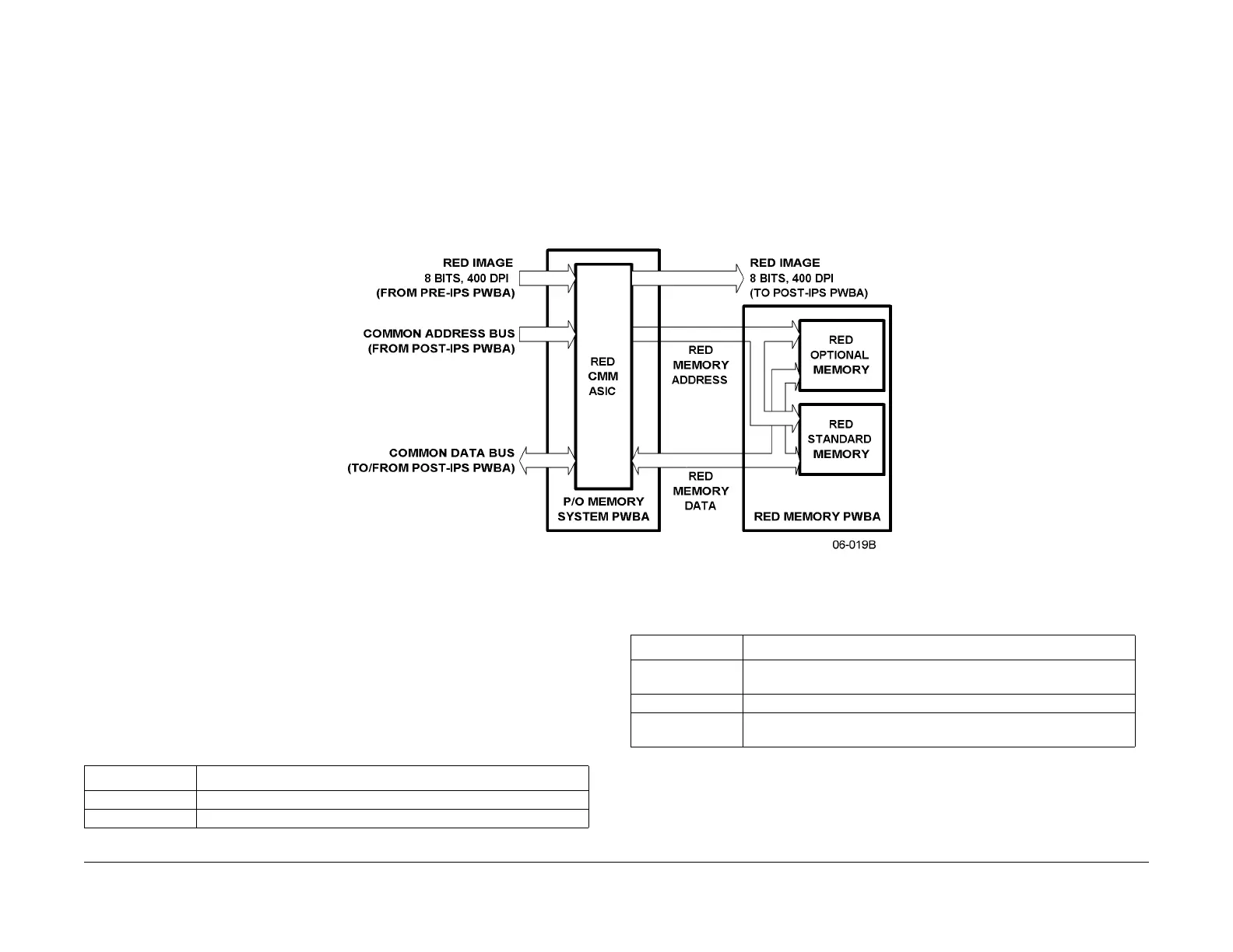
Each scanned image is stored in a memory subsystem comprising a Memory System PWBA
and three Memory PWBAs. As partially shown in Figure 2, the image is accepted by the Mem-
ory System PWBA from the Pre-IPS PWBA and is provided to the Post-IPS PWBA. Each
image pixe
l is
defined by eight bits for each of three colors: red, green and blue. The images
are actually stored in three Memory PWBAs, one per color. Each Memory PWBA has a stan-
dard capacity of 32 MBytes or an optional capacity of 64 MBytes of Random Access Memory
(RA
M). T
he standard 96 MB total RAM capacity is large enough to store a single 11” by 17”
image or two 8-1/2” by 11” images. The optional RAM capacity of all three Memory PWBAs
provides storage for 11” by 17” images.
Each Memory PWBA is controlled by a unique CMM, located on the Memory System PWBA.
T
he t
hree CMMs are themselves controlled by common address and data buses from the Post-
IPS PWBA.
Figure 2 Red Memory Simplified Block Diagram
Post-IPS
The Post-IPS PWBA (Figure 3) processes 8-bit RGB image pixels retrieved from the Memory
PWBA and provides them in YMCK (yellow, magenta, cyan, black) format to the Video Select
PWBA. The Post-IPS PWBA first converts the RGB data to a L*a*b* format. This intermediate
data can be passed to and from the optional Edit PWBA. All of the board’s functionality is con-
tained in the ASICs listed in T
able 2,
which also describes the functions included in the
devices.
The Post IPS PWBA retrieves the RGB information from the Memory PWBA four times on a
pixel by
pixel basis.
This is because all three input values are required to construct all four out-
put values. The image’s pixel color information is provided to the VSEL PWBA circuitry four
t
im
es, once per output color, in the following order:
Table 2 Post-IPS PWBA ASICs and Their Functions
ASIC Name Functions
CST Converts image from RGB format to L*a*b* format
MAX (3 total) Differentiates between text and image areas of document original
TRE Enlarges/Reduces in one dimension; Creates mirror image; Shifts
Image
TBC Converts 400 DPI to 600 DPI; generates ti
ming signals
CPI Generates chip selects; Contains priority interrupt controller; Gener-
ates delay signals
Table 2 Post-IPS PWBA ASICs and Their Functions
ASIC Name
Functions
manuals4you.commanuals4you.com

 Loading...