1/05
10-138
DocuColor 12/DCCS50
Functional Description of Fuser Subassemblies
Reissue
Principles of Operation
Copy Transport and Sensors
The unfused print is transported from the IBT Belt to the Fuser by the Vacuum Belt. A Fuser
Entrance Sensor just before the Vacuum Transport Assembly is used to detect paper jams from
the IBT by sensing the lead edge and trail edge of the copy. The lead edge of the copy is
guided into the Contact Arc of the Fuser by the Inlet Chute.
Stripper Fingers on the Pressure Roller and Heat
Roller help prevent t
he copy from wrapping
around these Rollers. As the copy leaves the Fuser nip, the lead edge enters the nip of the
Fuser Exit Rollers. A Fuser Exit Sensor detects the lead edge of the copy as it leaves the Fuser
Exit Rollers. This sensor looks for the lead edge of the copy as it exits the Fuser. If the lead
edge is more than 20 ms late to this sensor, the Fuser will stop, the Fuser nip will open and a
jam error code will be generated. The quick stopping of the Fuser helps prevent the copy from
getting wrapped around the Heat or Pressure Rolls. Copy jams of this type can always be
cleared from the Fuser entrance area.
Refer to Standby Power, Section 1 for information on machine safety interlocks.
Temperature Control and Power Usage
The Fuser Assembly includes three heated rollers. Each of these rollers have Tungsten Halo-
gen Quartz Lamps in their centers, and the heat generated by the lamp migrates to the surface
of th
e roller for the fusing process.
Fuser temperature control is complicated and as shown in Figu
re 3. there are four classes of
required components:
1. Thermistors to measure the temperature of each Fuser roll.
2. Lamps to heat the rolls
3. Control hardware and software to read the temperature and switch the lamps on and off.
4. Thermostats to prevent the Fuser from catastrophically overheating due to a component
failure.
To
monitor and regulate the Fuser heating cycles, each roll has two thermistors (Table 3) and a
ther
mostat on or near the external surfaces of the rolls. The functions of each are as follows:
• Control Thermistors - Th
ese determine the nominal set and run temperatures of the
associated roll. The current through these devices is monitored by the IOT Drive and Con-
trol PWBAs. These are in direct contact with each roll.
• O
verheat Thermistors - These a
re also monitored by the IOT Drive and Control PWBAs.
When the current through one of these devices reaches a particular value, the IOT Con-
trol and Drive PWBAs attempt to completely shut off the heater for the associated roll.
T
hi
s occurs when the thermistors sense a temperature of 230° C or more. These Ther-
mistors are in direct contact with each roll.
• O
verheat Thermostats - Th
ese are Fail-Safe switches. When a Thermostat senses an
overheat condition (>230° C), it opens and disconnects power from the associated heat
lamp. the Thermostats are spaced approximately 3 mm from the surface of each Roll.
These thermostats cannot be reset.
• The Heat Ro
ll
(HR) is 65mm in diameter, with a 4.5mm aluminum thick wall and 3mm Sil-
icon Rubber base coating and a layer of Viton on the outs
ide. The Heat Roll has priority
over the other two rolls for power required for the heat lamp. The Heat Roll has its own
drive motor for copy transport.
• The P
ressure Ro
ll (PR) is 65mm in diameter, with a 4.5mm aluminum thick wall and a
2mm Silicon Rubber base coating and a layer of Viton on the outside. The Pressure Roll
is mounted on brackets, which cam up to the bottom of the Heat Roll to create the Fuser
Contact Arc. The Pressure Roll is gear driven by the Fuser Motor.
• The E
xternal Heat Roll (EHR)
is a 23mm diameter stainless steel roll with a 2.5mm thick
wall. Its purpose is to help regulate the surface temperature of the Heat Roll by applying
additional heat directly to the surface of the Heat Roll. This reduces variations in tempera-
ture of the Heat Roll surface. The External Heat Roll rotation comes from direct contact
wit
h the
motor driven Heat Roll.
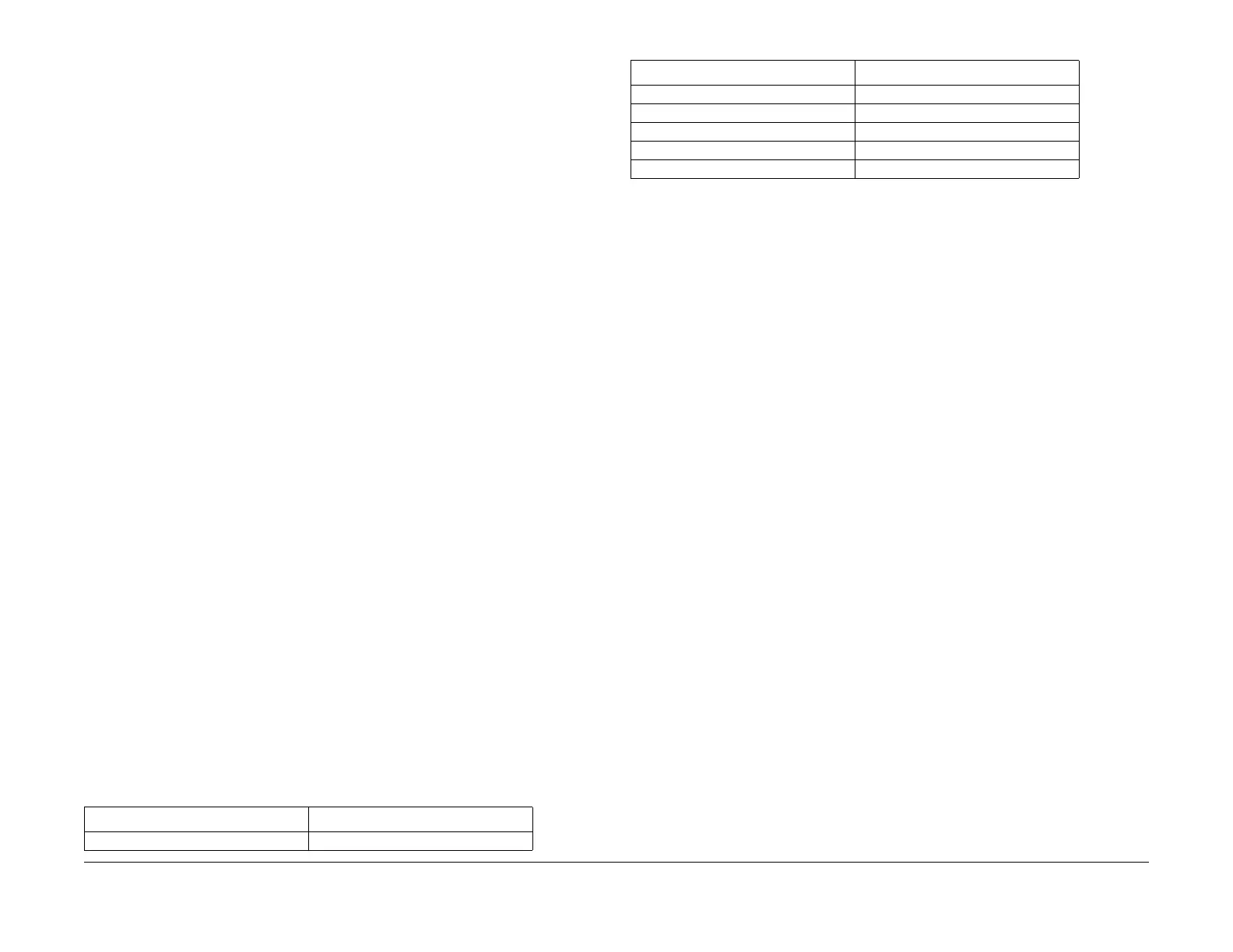
Table 3 Fuser Thermistor Resistance Values
Thermistor Temperature (°C) Thermistor Resistance (kOhms)
20 102 - 150
50 10 - 40
100 5.7 - 6.9
130 2.46 - 2.95
160 1.22 - 1.35
180 0.78 - 0.87
Table 3 Fuser Thermistor Resistance Values
T
hermi
stor Temperature (°C) Thermistor Resistance (kOhms)
manuals4you.commanuals4you.com

 Loading...