1/05
10-122
DocuColor 12/DCCS50
Development, Intermediate Belt Transfer (IBT)
Reissue
Principles of Operation
• During Max Setups (in Diagnostics)
• During Mini Setups
• During run mode after every 26th copy for A4 or 8 1/2 x 11 inch copies
• During run mode after every 13th copy for A3 or 11 x 17 inch copies
The readings are used by Process Controls to det
ermi
ne the developer dispensing run time.
Refer to Process Controls for more information on this function.
The dynamic range of the ADC S
ensor is fr
om 0% to about 80% area coverage. The ADC
patches are made at area coverage of 60% (for black toner) or 65% (for yellow, magenta and
cyan toner). In addition, for a given coverage, the black patch reflects less light than the
remaining colors. These two factors result in differences in sensor outputs: Vpatch, and affects
the ratio Vpatch / Vclean. Later circuitry compensates for these differences.
The physical positioning of the ADC Sensor is critical.
• The distance between the ADC Sensor and the IBT Belt must be 8mm, ± 0.5 mm
• The sensor angle with the IBT Belt must be less than ± 2° in t
he process
direction and
less than ±1° across the belt.
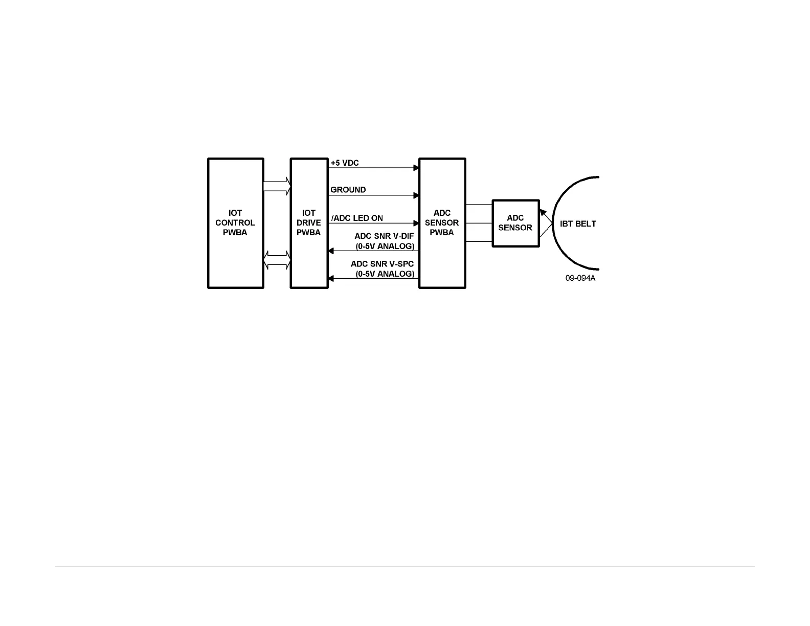
Figure 10 ADC Sensor Simplified Block Diagram
Intermediate Belt Transfer (IBT)
Toner Transfer Overview
Intermediate Belt Transfer (IBT) is new technology for this type of machine. This technology
permits increased color print speed and higher image quality. Using an IBT results in two
image transfer points.
1. The first image transfer point is from the Photoreceptor Drum
to the IBT (the colors trans-
fer one at a time from the Drum to the IBT.)
2. The second image transfer is the complete image for the IBT to the copy material. (All
col
or layer transfer in one pass.)
When making color images, one color at a time is developed on t
he Photoreceptor Drum and
then transferred to the IBT before the next color is used to develop the latent image on the Pho-
toreceptor Drum. The IBT Belt accumulates all four separate color images from the Photore-
ceptor (PR) Drum. During a four color image copy job, the IBT Belt cycles four times to accept
t
he
individual colors from the Photoreceptor Drum.
Because the toner transfer process occurs in two steps (PR Drum to IBT Belt, then IBT Belt to
copy mate
rial), the image and the layers of toner on the IBT are reversed from what the fin-
ished copy is.
After each image is developed on the Photoreceptor
Dr
um, the Drum rotates clockwise to
make contact with the IBT Belt, which is rotating counter clockwise. This contact occurs at the
First Bias Transfer Roll (1st BTR) position on the Belt. The 1st BTR and Photoreceptor Drum
create a nip, through which the IBT Belt passes. The 1st BTR roll always remains in contact
with the back side of the IBT Belt, and the IBT Belt is always in contact with the Photoreceptor
Drum. (The 1st BTR Roll is cammed away from the Photoreceptor Drum by the IBT lever on
the IBT Drawer. This is done when sliding this drawer open or closed.)
The 1st BTR inside the IBT Assembly is charged t
o +32 mi
croamps at +1200 VDC by the 1st
BTR HVPS. This causes the negatively charged toner on the PR Drum to be attracted to the
surface of the IBT Belt at this 1st BTR point. The charge to the 1st BTR remains on from the
start to the end of a job.
When all four color image components have been transferred to the IBT, this image is trans-
ferred to the final copy material using one pas
s.
This second image transfer takes place where
the IBT Belt contacts the Second Bias Transfer Roll (2nd BTR).
The 2nd BTR is part of a separate assembly, below the IBT Assembly. This 2nd BTR Assembly
includes:
• Inlet Plate
• Pre IBT Sensor (for the paper path)
manuals4you.commanuals4you.com

 Loading...