1/05
4-197
DocuColor 12/DCCS50
ADJ 8.1.1, ADJ 8.8.1
Repairs and Adjustments
Reissue
ADJ 8.1.1 Fuser Nip (DC701)
Purpose
To make a copy for checking and adjusting the Fuser Nip Width.
Check
NOTE: Use Tray 5 for making a measurement copy and a nip width measurement.
The paper used for the nip width measurement differs depending on the market:
• XE, FX: A4L (90GSM Colotech+)
• XC, XCL, AO: Letter L (24# Color Expressions)
1. Enter dC701 F
user
Nip Measurement.
(PC-Diag. screen: Adjustment/Other Adjustment/Set Fuser Nip Adjustment)
2. Place the specified paper in Tray 5.
3. Follow the instructions on the screen and print three measurement copies.
4. Place the copies just made back into Tray 5, face up.
5. Select M
ake wi
dth measurement repeat this three times.
6. Check that the nip width is an average of 10.3 +/- 0.3mm, front to rear.
Adjustment
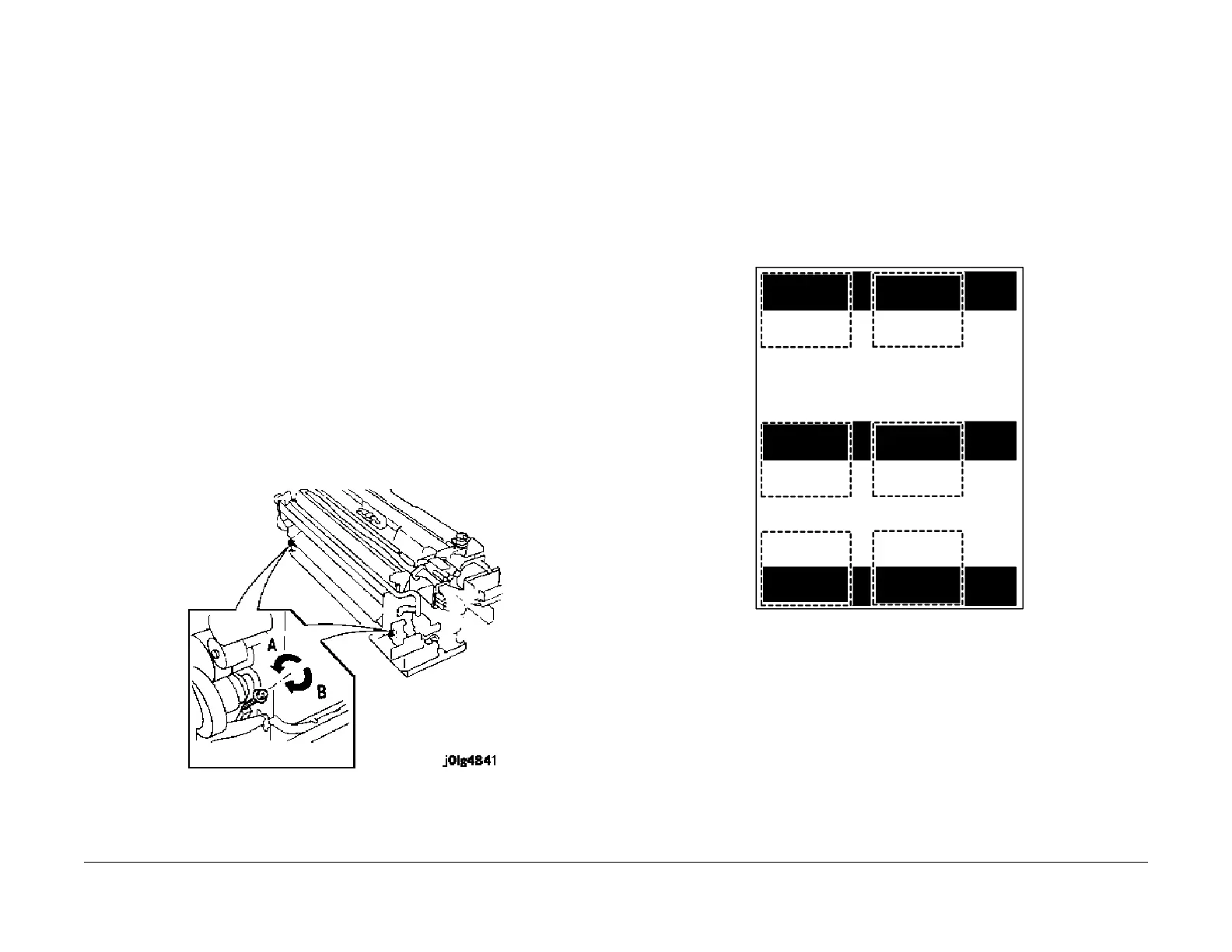
1. Adjust the screw (located on side requiring nip width adjustment) (Figure 1).
1. Rotate in the A direction (CCW): nip width becomes smaller.
2. Rotate in the B direction (CW): nip width becomes larger.
NOTE: 1/2 turn = approximately 0.5mm nip width change.
Figure 1 Adjust the Nip
2. Repeat the check and adjustment until the Nip Width is within specification.
ADJ 8.8.1 External Heat Roll Nip Adjustment
Purpose
The purpose of this adjustment is to ensure correct Heat Roll-to-External Heat Roll contact,
which will aid in proper fusing and minimize web wrapping.
Check
1. Enter DC701 (PWS Tool) or Subsystem Check / Fuser Nip Measurement from the UI
diagnostic screen.
2. Place 24lb (90gsm) 8.5 x 11 LEF paper in Tray 5.
3. Select Nip Adjustment Black Copy and make 1 copy.
4. Cut the copy to make 6 - 70 mm x 60mm test strips as shown in Figure 1.
F
igure 1 dC701 Test Page
5. Fold each test strip along the edge where the black and white portions meet.
6. Open the Front Door and pull the Drawer Assembly out to the maintenance position (RE
P
8.
1.1).
7. Remove the Fuser Top Cover (PL 8.2 item
1).
8. Install a cheater in the Front Door Interlock, and allow the machine to come to Ready.
NOT
E: If strips will not fit between Heat and External Heat Roll, close copy drawer for approxi-
mately. 3 seconds and open drawer to install strips. If, after doing this several times, you can-
not position the strips, replace the assem
bly
because the frame is bent.
9. Insert 2 folded test strips (Figure 2
) between Heat Roll and External Heat Roll approxi-
mately 50 mm from ends of rolls.

 Loading...