1/05
10-70
DocuColor 12/DCCS50
Image Sensing (Digital Copier & Copier/Printer Con-
Reissue
Principles of Operation
Image Sensing (Digital Copier & Copier/Printer
Configuration)
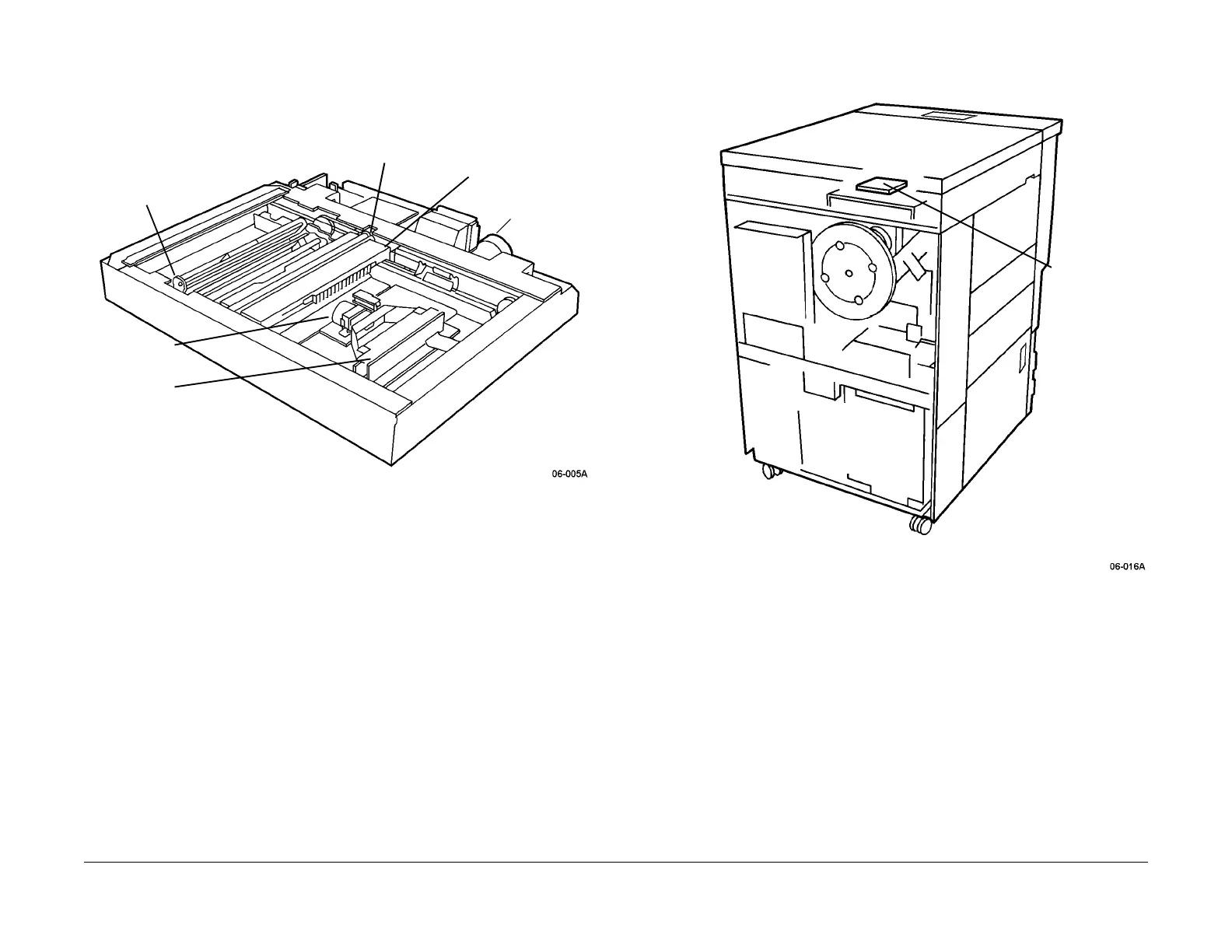
The image sensing components are shown in Figure 2 and Figure 3.
Figure 1 Scanning Optical System Mechanical Components Locations
Figure 2 Motor/Lamp/Fan Drive PWBA Location
Xenon Lamp and Drive Circuitry
A Xenon Lamp (Figure 1) is used in this machine as a means of reducing heat. Unlike incan-
descent Lamps, including quartz Lamps, the illumination of Xenon Lamp is not continuous It
varies direc
tly with the instantaneous voltage of the driving signal. This is similar to fluorescent
bulbs and means that if the driving signal is AC (Alternating Current), the bulb emits no light
when the instantaneous voltage is zero.
If the bulb drive frequency is 60 Hz or higher, the h
uman ey
e sees this as a constant level of
illumination. However, the CCDs on the CCD PWBA are fast enough to see the change in illu-
mination caused by the AC drive signal used for the Xenon Lamp. Therefore, the CCD must
capt
ure it
s image when the Xenon Lamp outputs are known to be non-zero.
Two techniques are used to compensate for this:
HALR-RATE
CARRIAGE
CCD LENS
CCD ARRAY
FULL-RATE
CARRIAGE
XENON LAMP
CARRIAGE
MOTOR
MOTOR/
LAMP/FAN
DRIVE PWBA
manuals4you.commanuals4you.com

 Loading...