1/05
2-227
DocuColor 12/DCCS50
OF19-1 IDFE Fault Entry RAP
Status Indicator RAPs
Reissue
OF19-1 IDFE Fault Entry RAP
NOTE: There are two configurations of the IDFE for this machine. They are identifiable by the
Product Code on the ID tag and by the number of Diagnostic LEDs. Early versions have 5
LEDs and are labeled Product Code GL2. Later versions have 6 LEDs and are labeled Product
Code MFY. This RAP applies generically to both. Where differences between the units exist,
the applicable information is followed by the product code for the specific IDFE.
NOTE: Centerware Network Services is the official name for “web client” and “web UI.”
NOTE: The IOT does not log or display Integrated Digital Front End (IDFE) fault codes.
This RAP is intended to help analyze the fault code(s), indicated by the LED display on the
I
DF
E, or by the Configuration Report and to direct the field service representative to the appli-
cable RAP.
Initial Actions
• Refer to BSD 16.1.
• Verify that the DC wire harness connector, P/J 889 is correctly seated into the IDFE.
• From your machine log, obtain the Configuration Report and verify that the version of firm-
ware and software for the IDFE and the IOT are compatible.
Procedure (Product Code GL2)
NOTE: Before evaluating the fault indicated by the Diagnostic LEDs, allow 70-180 seconds to
pass for the Diagnostic LEDs to come to a steady state condition after the IDFE has been
switched-on.
NOTE: If more than one fault is detected the first error encountered is the one displayed.
NOTE: If a hard fault is detected during power up, the software boot sequence test stops. If a
soft f
ault is detected, the Software boot process will continue.
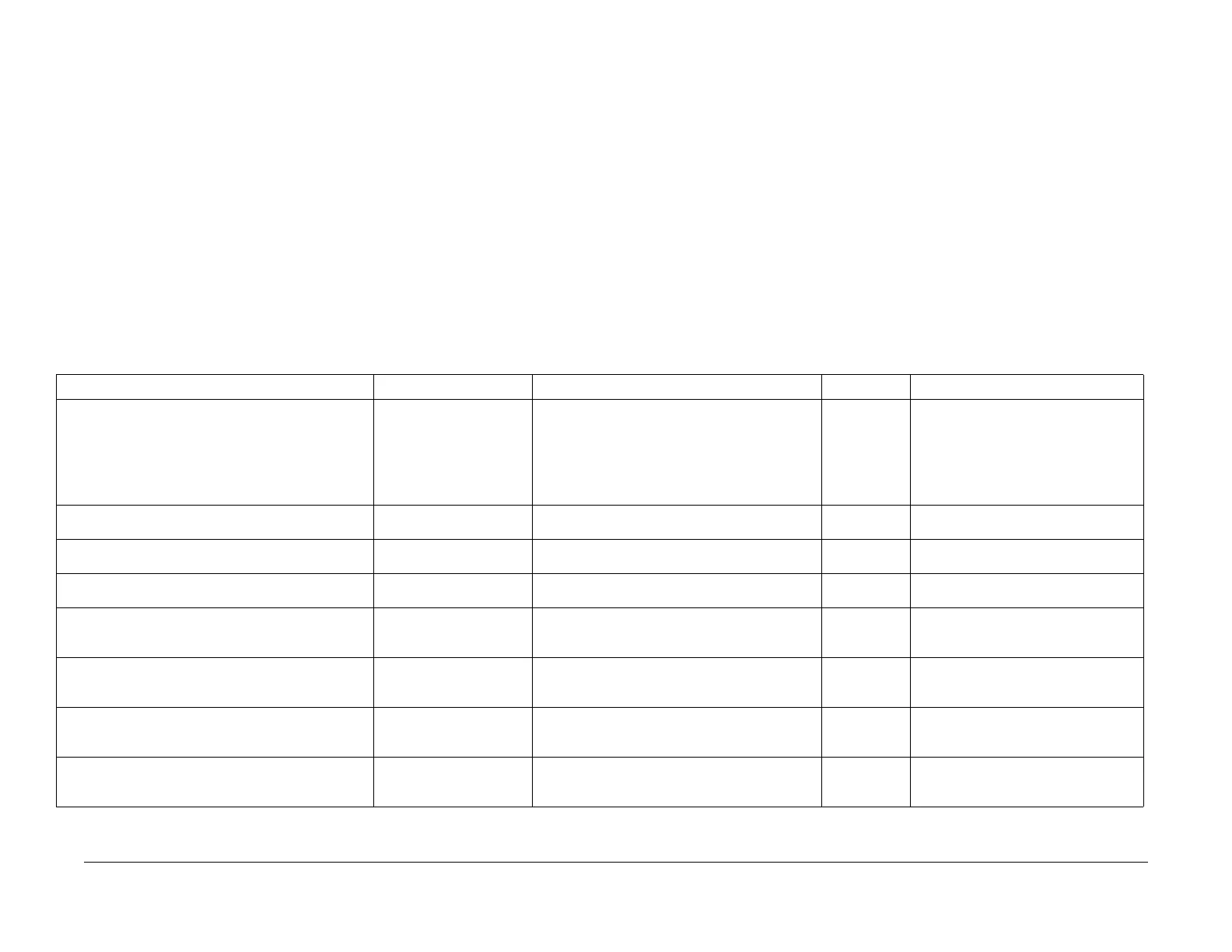
Switch on the power. Observe the IDFE Diagnostic LEDs (Figure 1
) as the system performs
self -test. Compare the observations with the Fault Indication descriptions in Table 1 and
Table 2. Refer to Table 3 for a description of the function of each LED.
Table 1 Power-on Self Tests (GL2)
Fault Indication Fault Go to RAP: Type of Fault Comments
Within 10 seconds of Power-On if any of the LEDs on the
I
DF
E are de-energized or if the Green Power LED is de-
energized.
NOTE: After a PO/PO is performed all LEDs should
en
ergize f
or approximately 10 seconds. If this does not
occur, perform RAP 19-001.
DC Power Fault 19-001 DC Power Fault RAP Hard IDFE does not log or display fault.
Red Failure LED is energized continuously. Booting or Hardware Fail-
ure
19-002 BIOS/Self-Test Fault RAP Hard IDFE does not log or display fault.
Amber Heartbeat LED is energized continuously or de-
en
ergized continuous
ly
Software Load Halted 19-003 Hard Disk Fault RAP Hard IDFE does not log or display fault.
Amber Heartbeat LED is energizes for 0.5 seconds and
de-energizes f
or 0.5 seconds.
Software Running Normal operation when software is run-
ning.
Red Failure LED energizes for 0.25 seconds and de-
energizes f
or 2.0 seconds in a continuously repeated
pattern.
DDI IOT Failed Internal
Loop bac
k Test
19-004 Printer DDI Communication Fault 1 RAP Hard IDFE does not log or display fault, web UI
remains active
Red Failure LED energizes twice in 0.25 second inter-
vals, then de-energizes for 2 seconds. This pattern is
c
ontinuous
ly repeated.
DDI IOT Failure, End to
End (Cable,
IO
T or IDFE
Failure)
19-005 Printer DDI Communication Fault 2 RAP Soft IDFE does not log or display fault, web UI
r
emains active
Red Failure LED energizes three times in 0.25 second
int
ervals
, then de-energizes for 2 seconds. This pattern
is continuously repeated.
DDI IOT Failed Internal
Loop bac
k Test
19-006 Scanner DDI Communication Fault 1 RAP Hard Printer and web UI remain active
Red Failure LED energizes four times in 0.25 second
intervals
, then de-energizes for 2 seconds. This pattern
is continuously repeated.
DDI IOT Failure, End to
End (Cable,
IOT or IDFE
Failure)
19-007 Scanner DDI Communication Fault 2 RAP Soft Printer and web UI remain active

 Loading...