1/05
10-188
DocuColor 12/DCCS50
Power Distribution - Solid State Relay, Power Distri-
Reissue
Principles of Operation
Power Distribution - Solid State Relay
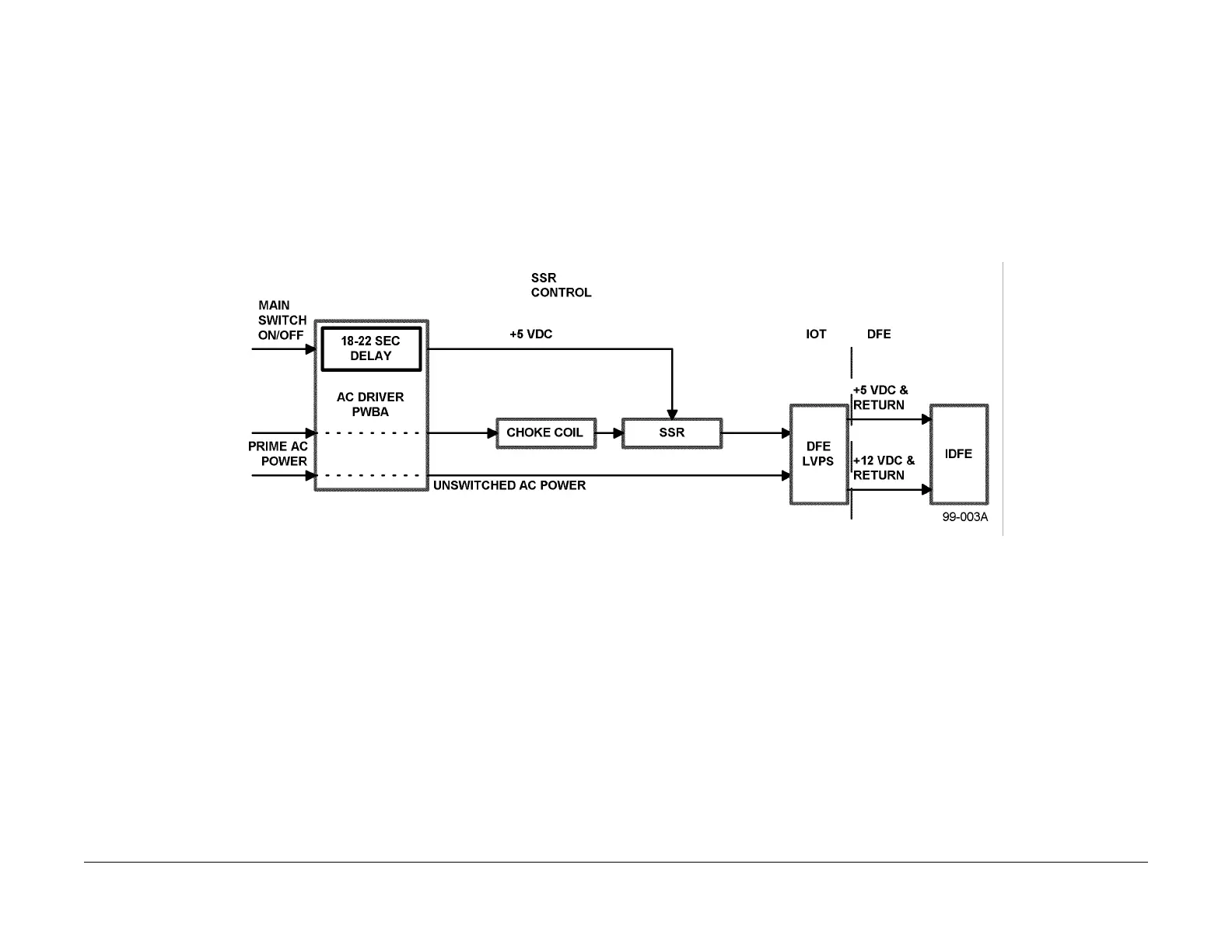
The AC Driver PWB supplies +5 VDC to the Coil of the Main Switch (BSD 1.1). When the Main
Switch is pressed, the Coil for the Switch is energized, providing +5 VDC to Connector J83 Pin
1 of the Printer Solid State Relay (SSR) (BSD 16.1). To complete the DC circuit, Connector J84
Pin 1 provides the return path to ground from the SSR to the AC Driver PWBA at Connector
J20 Pin 2.
From Connector J2 (BSD 16.1), the AC Driver PW
BA
(PL 9.3) provides 120 VAC @ 16
amperes (220/240 VAC @ 10 Amperes) to Connector J81 Pin 1 of the Printer SSR (PL9.3).
When this DC circuit is energized, the SSR will switch on, allowing high voltage AC from the AC
Driver PWBA to pass through the Printer SSR to Connector J82 Pin 1 and onto Connector J4
Pin 4 of the Printer Low Voltage Power Supply (LVPS).
NOTE: When an operator removes power from the IOT by switching off the main switch, an
RC net
wo
rk located on the AC Driver PWBA delays release of the Coil for the Main Switch for
18-22 seconds. This delay is used to allow the IDFE Hard Disk Drive to safely shut down (Fig-
ure 1).
Power Distribution - Printer Low Voltage Power Supply
(LVPS)
When energized, the Printer SSR provides 120 VAC @ 16 Amperes (220/240 VAC @ 10
Amperes) to the Printer LVPS at Connector J4 Pin 4 (BSD 16.1). The Printer LVPS converts
this AC power into a regulated +5.1 VDC @ 11 Amperes Power Supply, and a regulated +12
VDC @ 1.6 Amperes Power Supply within the LVPS (BSD 16.1).
Figure 1 IDFE Power Interface Block Diagram
NOTE: There is a ground wire attached to the Chas
sis Fr
ame at P/J 899 Pin 12. This is not
shown on BSD 16.1.
NOTE: The Printer and IOT LVPS are separate. The Printer LVPS is located behind the AC
Driver PW
BA.
The return path to Frame Ground for the Printer LVPS is provided through Connector J4 Pin 1
(BSD 1
6.1).
Power Distribution - IDFE
The IDFE (PL 19.1) is an enclosed color server mounted on the back of the DocuColor 12,
which converts the IOT into a network printer. The IDFE uses +5 VDC power, supplied from the
Printer LVPS to power the following parts inside the IDFE (PL 19.1):
• IDFE Motherboard
• Diagnostic LEDs
• CD-ROM Drive
• Token Ring PWBA
• Hard Disk Drive
The DC returns for the IDFE Motherboard, CD-ROM Drive, Token Ring PWBA and the Hard
Disk Drive are provided thr
ough the Connector P/J 899 Pins 5, 6, 7,and 8 (BSD 16.1) to Con-
nector J508 Pins 3 and 4 on the Printer LVPS.
manuals4you.commanuals4you.com

 Loading...