CRANKSHAFT
5-87
EAS25980
REMOVING THE CRANKSHAFT AND BAL-
ANCER SHAFT
1. Remove:
• Balancer shaft “1”
• Balancer shaft journal bearings
• Crankshaft assembly “2”
• Crankshaft journal bearings
Identify the position of each balancer shaft
journal bearings and crankshaft journal bear-
ings so that it can be reinstalled in its original
place.
EAS14B1025
CHECKING THE OIL NOZZLES
The following procedure applies to all of the oil
nozzles.
1. Check:
• Oil nozzle “1”
Damage/wear → Replace the oil nozzle.
• Oil passage
Obstruction → Blow out with compressed
air.
EAS14B1026
CHECKING THE CRANKSHAFT
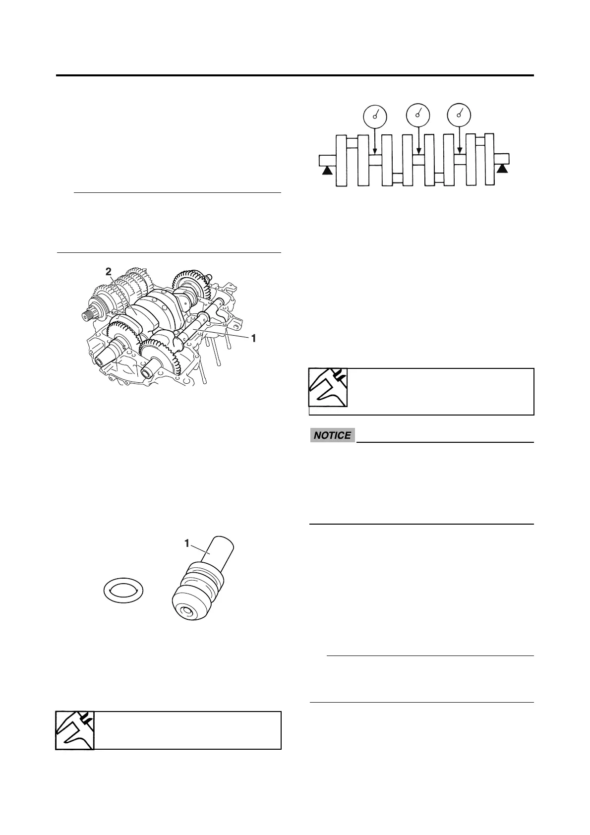
1. Measure:
• Crankshaft runout
Out of specification → Replace the crank-
shaft.
2. Check:
• Crankshaft journal surfaces
• Crankshaft pin surfaces
• Bearing surfaces
Scratches/wear → Replace the crank-
shaft.
3. Measure:
• Crankshaft-journal-to-crankshaft-journal-
bearing clearance
Out of specification → Replace the crank-
shaft journal bearings.
ECA13920
Do not interchange the crankshaft journal
bearings. To obtain the correct crankshaft-
journal-to-crankshaft-journal-bearing clear-
ance and prevent engine damage, the
crankshaft journal bearings must be
installed in their original positions.
▼▼▼▼▼▼▼▼▼▼▼▼▼▼▼▼▼▼▼▼▼▼▼▼▼▼▼▼▼▼
a. Clean the crankshaft journal bearings,
crankshaft journals, and bearing portions of
the crankcase.
b. Place the upper crankcase upside down on
a bench.
c. Install the crankshaft journal upper bear-
ings “1” and the crankshaft into the upper
crankcase.
Align the projections “a” on the crankshaft jour-
nal upper bearings with the notches “b” in the
upper crankcase.
Crankshaft runout limit
0.030 mm (0.0012 in)
Journal oil clearance
0.004–0.039 mm (0.0002–
0.0015 in)
 Loading...