ELECTRICAL COMPONENTS
8-133
b. Turn the main switch to “ON” and engine
stop switch to “ ”.
c. Measure the ignition spark gap “a”.
d. Crank the engine by pushing the start
switch “ ” and gradually increase the
spark gap until a misfire occurs.
▲▲▲▲▲▲▲▲▲▲▲▲▲▲▲▲▲▲▲▲▲▲▲▲▲▲▲▲▲▲
EAS28120
CHECKING THE CRANKSHAFT POSITION
SENSOR
1. Disconnect:
• Crankshaft position sensor coupler
(from the wire harness)
2. Check:
• Crankshaft position sensor resistance
Out of specification → Replace the crank-
shaft position sensor.
▼▼▼▼▼▼▼▼▼▼▼▼▼▼▼▼▼▼▼▼▼▼▼▼▼▼▼▼▼▼
a. Connect the pocket tester (Ω × 100) to the
crankshaft position sensor coupler as
shown.
b. Measure the crankshaft position sensor
resistance.
▲▲▲▲▲▲▲▲▲▲▲▲▲▲▲▲▲▲▲▲▲▲▲▲▲▲▲▲▲▲
EAS28130
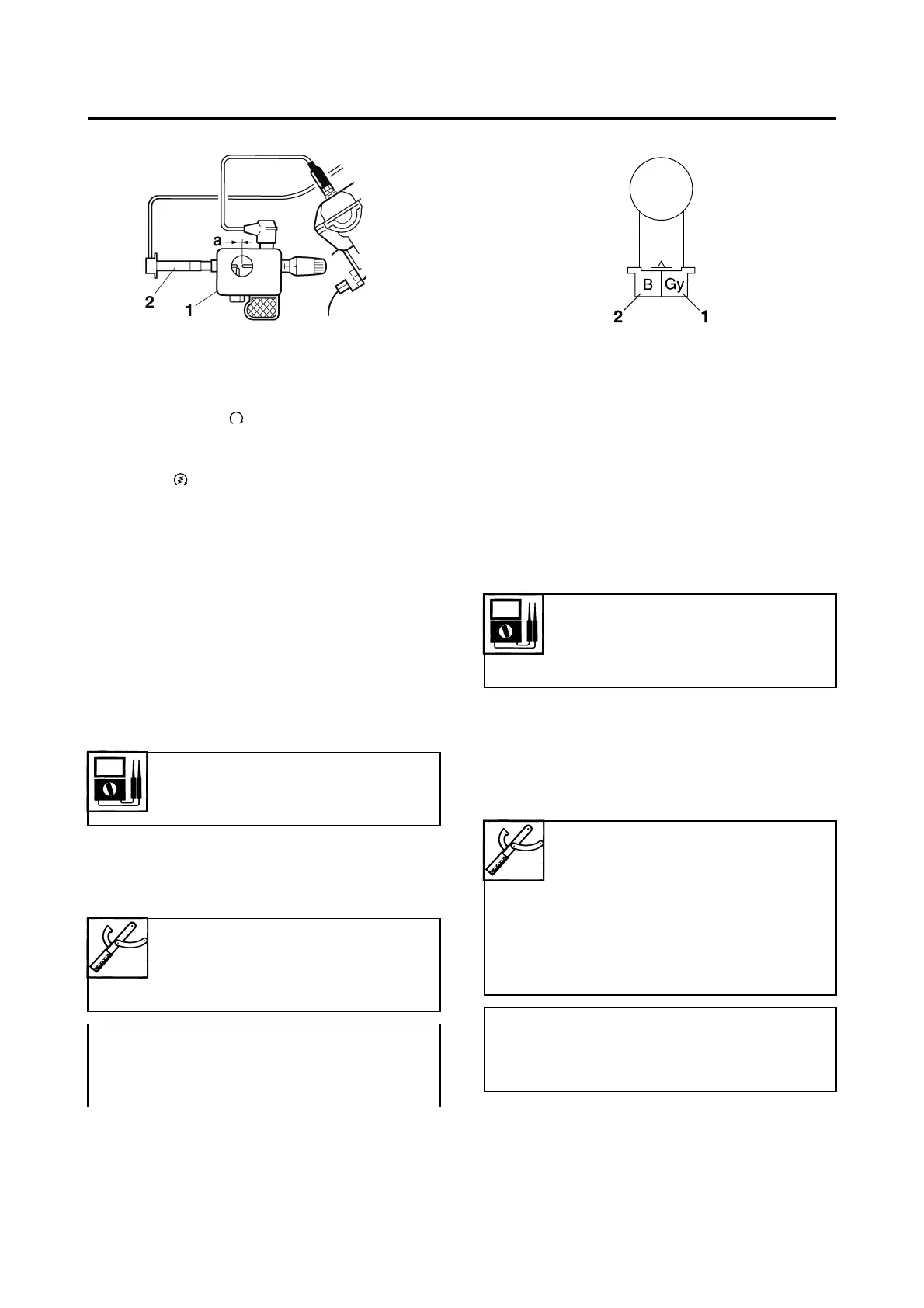
CHECKING THE LEAN ANGLE SENSOR
1. Remove:
• Lean angle sensor
(from the battery box 2)
2. Check:
• Lean angle sensor out put voltage
Out of specification → Replace.
▼▼▼▼▼▼▼▼▼▼▼▼▼▼▼▼▼▼▼▼▼▼▼▼▼▼▼▼▼▼
a. Connect the test harness-lean angle sen-
sor (6P) “1” to the lean angle sensor and
wire harness as shown.
b. Connect the pocket tester (DC 20 V) to the
test harness-lean angle sensor (6P).
2. Ignition coil
Crankshaft position sensor
resistance
248–372 Ω at 20 °C (68 °F)
Pocket tester
90890-03112
Analog pocket tester
YU-03112-C
• Positive tester probe
Gray “1”
• Negative tester probe
Black “2”
Lean angle sensor output volt-
age
Less than 45°: 0.4–1.4 V
More than 45°: 3.7–4.4 V
Pocket tester
90890-03112
Analog pocket tester
YU-03112-C
Test harness-lean angle sensor
(6P)
90890-03209
YU-03209
• Positive tester probe
Yellow/Green (wire harness color)
• Negative tester probe
Black/Blue (wire harness color)

 Loading...