ELECTRICAL COMPONENTS
8-141
c. Turn the main switch to “ON”.
d. Measure the atmospheric pressure sensor
output voltage.
▲▲▲▲▲▲▲▲▲▲▲▲▲▲▲▲▲▲▲▲▲▲▲▲▲▲▲▲▲▲
EAS28390
CHECKING THE CYLINDER IDENTIFICA-
TION SENSOR
1. Remove:
• Fuel tank
Refer to “FUEL TANK” on page 7-1.
• Air filter case
Refer to “AIR FILTER CASE” on page 7-
5.
• Air filter case duct
Refer to “AIR INDUCTION SYSTEM” on
page 7-21.
2. Check:
• Cylinder identification sensor output volt-
age
Out of specification → Replace.
▼▼▼▼▼▼▼▼▼▼▼▼▼▼▼▼▼▼▼▼▼▼▼▼▼▼▼▼▼▼
a. Connect the test harness-speed sensor
(3P) “1” to the speed sensor coupler and
wire harness as shown.
b. Connect the pocket tester (DC 20 V) to the
test harness-speed sensor (3P).
c. Turn the main switch to “ON”.
d. Rotate the crankshaft.
e. Measure the voltage. With each full rotation
of the crankshaft, the voltage reading
should cycle from 0.8 V to 4.8 V to 0.8 V to
4.8 V.
▲▲▲▲▲▲▲▲▲▲▲▲▲▲▲▲▲▲▲▲▲▲▲▲▲▲▲▲▲▲
EAS28410
CHECKING THE INTAKE AIR PRESSURE
SENSOR
1. Check:
• Intake air pressure sensor output voltage
Out of specification → Replace.
▼▼▼▼▼▼▼▼▼▼▼▼▼▼▼▼▼▼▼▼▼▼▼▼▼▼▼▼▼▼
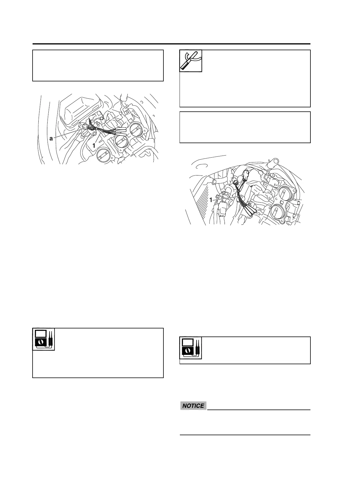
a. Connect the test harness S-pressure sen-
sor (3P) “1” to the intake air pressure sen-
sor and wire harness as shown.
ECA14B1035
Pay attention to the installing direction of
the test harness S-pressure sensor (3P)
coupler “a”.
• Positive tester probe
Pink (wire harness color)
• Negative tester probe
Black/blue (wire harness color)
Cylinder identification sensor
output voltage (ON)
More than 4.8 V
Cylinder identification sensor
output voltage (OFF)
Less than 0.8 V
Pocket tester
90890-03112
Analog pocket tester
YU-03112-C
Test harness-speed sensor (3P)
90890-03208
YU-03208
• Positive tester probe
White/Black (wire harness color)
• Negative tester probe
Black/Blue (wire harness color)
Intake air pressure sensor out-
put voltage
3.57–3.71 V at 101.32 kPa
 Loading...