ELECTRICAL COMPONENTS
8-130
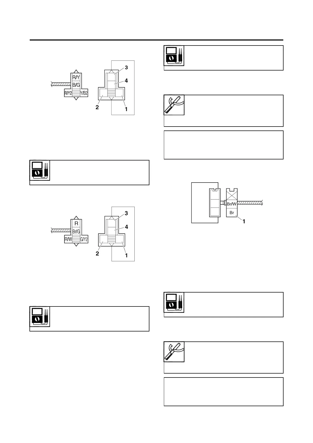
Headlight relay
Radiator fan motor relay
EAS14B1015
CHECKING THE TURN SIGNAL/HAZARD
RELAY
1. Check:
• Turn signal/hazard relay input voltage
Out of specification → The wiring circuit
from the main switch to the turn signal/
hazard relay coupler is faulty and must be
repaired.
▼▼▼▼▼▼▼▼▼▼▼▼▼▼▼▼▼▼▼▼▼▼▼▼▼▼▼▼▼▼
a. Connect the pocket tester (DC 20 V) to the
turn signal/hazard relay terminal as shown.
b. Turn the main switch to “ON”.
c. Measure the turn signal/hazard relay input
voltage.
▲▲▲▲▲▲▲▲▲▲▲▲▲▲▲▲▲▲▲▲▲▲▲▲▲▲▲▲▲▲
2. Check:
• Turn signal/hazard relay output voltage
Out of specification → Replace.
▼▼▼▼▼▼▼▼▼▼▼▼▼▼▼▼▼▼▼▼▼▼▼▼▼▼▼▼▼▼
a. Connect the pocket tester (DC 20 V) to the
turn signal/hazard relay terminal as shown.
1. Positive battery terminal
2. Negative battery terminal
3. Positive tester probe
4. Negative tester probe
Result
Continuity
(between “3” and “4”)
1. Positive battery terminal
2. Negative battery terminal
3. Positive tester probe
4. Negative tester probe
Result
Continuity
(between “3” and “4”)
Turn signal/hazard relay input
voltage
DC 12 V
Pocket tester
90890-03112
Analog pocket tester
YU-03112-C
• Positive tester probe
Brown “1”
• Negative tester probe
Ground
Turn signal/hazard relay output
voltage
DC 12 V
Pocket tester
90890-03112
Analog pocket tester
YU-03112-C
• Positive tester probe
Brown/White “1”
• Negative tester probe
Ground

 Loading...