108 ACS550-02/U2 User’s Manual
Application macros
PFC macro
This macro provides parameter settings for pump and fan control (PFC) applications.
To enable, set the value of parameter 9902 to 7 (
PFC CONTROL).
Note: Parameter 2108 START INHIBIT must remain in the default setting, 0 (OFF).
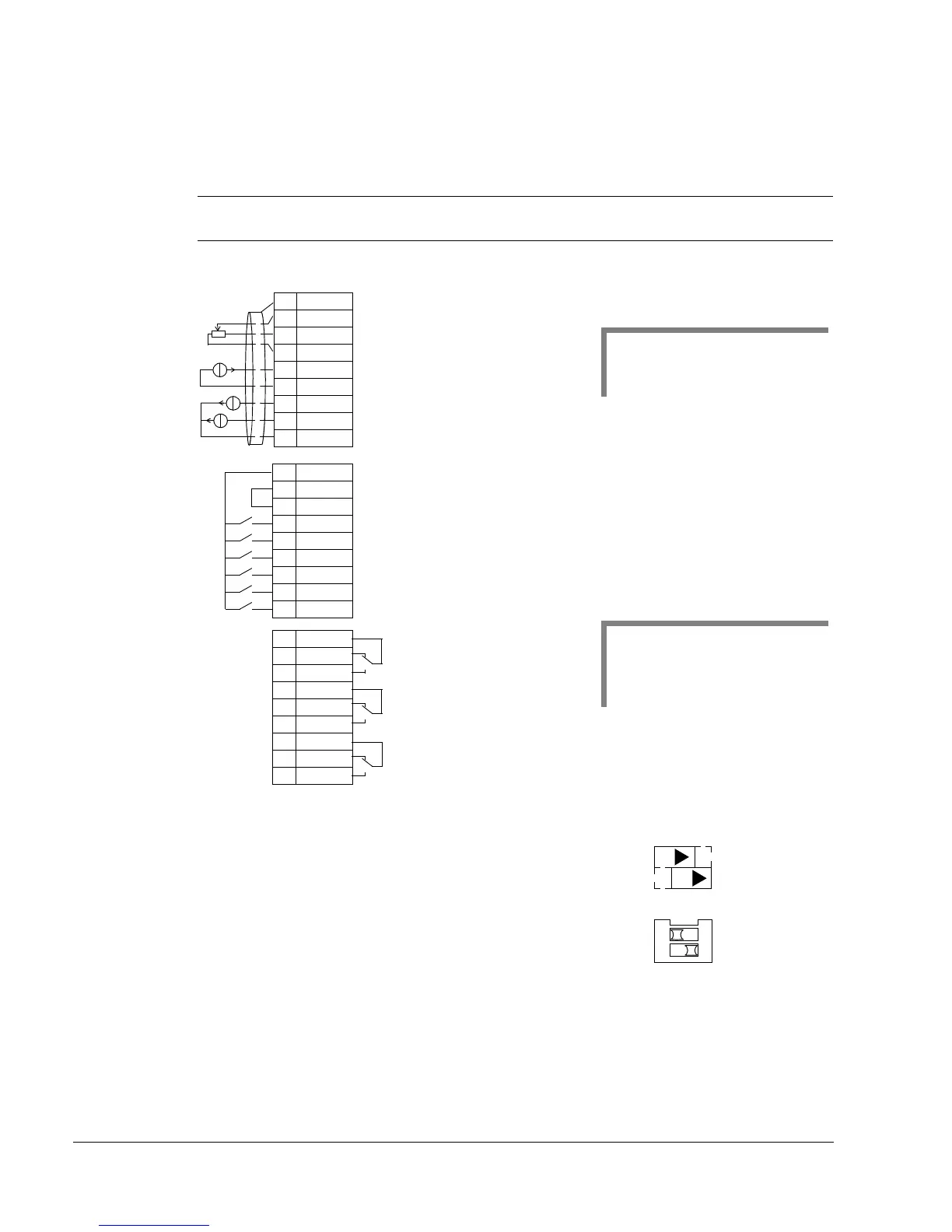
Connection example:
Input signals Output signals Jumper setting
• Analog ref. and actual (AI1, 2)
• Start/stop – manual/PFC (DI1, 6)
• Run enable (DI2)
• EXT1/EXT2 selection (DI3)
• Interlock (DI4, 5)
• Analog output AO1: Frequency
• Analog output AO2: Actual 1
• Relay output 1: Running
• Relay output 2: Fault (-1)
• Relay output 3: Aux. motor ON
or
Note: Use the following switch-on order:
1. EXT1/EXT2
2. Run Enable
3. Start.
EXT1/EXT2 selection: Activation selects PFC control
1SCR
2AI1
3AGND
410V
5AI2
6AGND
7AO1
8AO2
9AGND
10 24V
11 GND
12 DCOM
13 DI1
14 DI2
15 DI3
16 DI4
17 DI5
18 DI6
19 RO1C
20 RO1A
21 RO1B
22 RO2C
23 RO2A
24 RO2B
25 RO3C
26 RO3A
27 RO3B
Start/Stop (Manual): Activation starts the drive
Start/Stop (PFC): Activation starts the drive
Run enable: Deactivation always stops the drive
External ref. 1 (Manual) or Ext ref. 2 (PID/PFC): 0…10 V
1
Reference voltage 10 V DC
Output frequency: 0
…20 mA
Actual 1 (PI controller actual value): 0(4)
…20 mA
Analog input circuit common
Analog output circuit common
Auxiliary voltage output +24 V DC
Auxiliary voltage output common
Digital input common for all
Signal cable shield (screen)
Analog input circuit common
Actual signal (PID): 4
…20 mA
Interlock: Deactivation always stops the drive
Interlock: Deactivation stops constant speed motor
Note 1.
Manual: 0
…10V => 0…50 Hz
PID/PFC: 0
…10V => 0…100%
PID setpoint
Relay output 1, programmable
Default operation:
Relay output 2, programmable
Default operation:
Relay output 3, programmable
Default operation:
Running =>19 connected to 21
Fault (-1) =>22 connected to 24 (Fault => 22 connected to 23)
Auxiliary motor switched on=>25 connected to 27
2
Note 2.
The sensor needs to be powered.
See the manufacturer’s instructions.
A connection example of a two-wire
sensor is shown on page 110.
X1
1…10 kohm
J1
AI1: 0
…10 V
AI2: 0(4)
…20 mA
ON
ON
AI1: 0…10 V
AI2: 0(4)
…20 mA
ON
12
J1

 Loading...


