50 ACS550-02/U2 User’s Manual
Installation
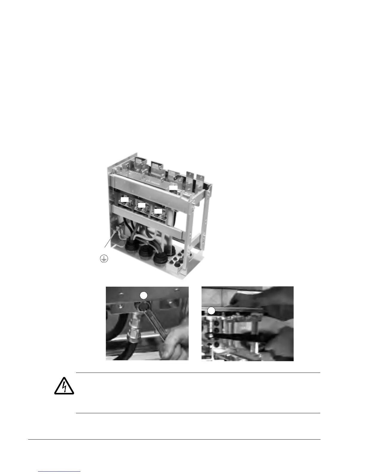
Connecting the cable lugs to the pedestal
1. If the lead-through plate is fixed to the floor, undo the fixing screws.
2. Place the pedestal onto the lead-through plate.
3. Fasten the pedestal and the lead-through plate to the floor with the screws through
the same holes.
4. Connect the cable lugs to the pedestal (U1, V1, W1, U2, V2, W2 and PE).
5. Tighten the connections
6. Frame size R7: Fasten the EMC screen between the input and motor cables as
shown in the figure on page 43.
WARNING! It is not allowed to connect the cables directly to the drive module
terminals. The lead-through insulation material is not strong enough to carry the
mechanical stress exerted by the cables. The cable connections must be performed
in the pedestal.
7. Wheel the drive frame back on the pedestal.
5
5
W2
V2
U2
UDC+
R+
UDC-
R-
W1
V1
PE
U1
Frame sizes R7 and R8:
M12 (1/2 in) bolt
Tightening torque: 50…75 N·m
(37…55 lbf·ft)
Frame size R7

 Loading...


