36 ACS550-02/U2 User’s Manual
Installation
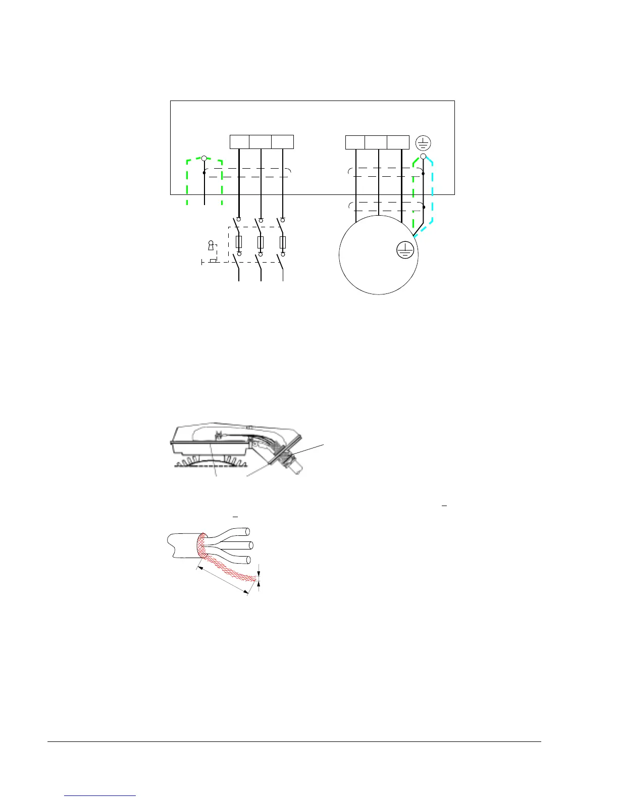
Power cable connection diagram
INPUT
OUTPUT
U1
V1
W1
3 ~
Motor
U1
V1 W1
1)
U2
V2 W2
L1 L2 L3
(PE) (PE)PE
1)
1)
2)
1) An alternative to the grounding of the drive and the motor through the cable shield or armour
Note: Connecting the fourth conductor of the motor cable at the motor end increases bearing
currents and causes extra wear.
2) Used if the conductivity of the cable shield is < 50% of the conductivity of the phase conductor.
3) For minimum radio frequency interference at the motor end:
• ground the cable shield 360 degrees at the lead-through of the motor terminal box
• or ground the cable by twisting the shield as follows: flattened width >
1/5 · length. In the
figure below, b >
1/5 · a.
360 degrees grounding
Conductive gaskets
a
b
Ground the other end of the input cable shield / PE conductor at the distribution board.
PE
3)
*

 Loading...


