170 ACS550-02/U2 User’s Manual
Parameters
Group 30: FAULT FUNCTIONS
This group defines situations that the drive should recognize as potential faults and
defines how the drive should respond if the fault is detected.
Code Description
3001 AI<MIN FUNCTION
Defines the drive response if the analog input (AI) signal drops below the fault limits and AI is used in reference chain.
• 3021 AI1 FAULT LIMIT and 3022 AI2 FAULT LIMIT set the fault limits
0 =
NOT SEL – No response.
1 =
FAULT – Displays a fault (7, AI1 LOSS or 8, AI2 LOSS) and the drive coasts to stop.
2 = CONST SP 7 – Displays an alarm (2006, AI1 LOSS or 2007, AI2 LOSS) and sets speed using 1208 CONST SPEED 7.
3 =
LAST SPEED – Displays an alarm (2006, AI1 LOSS or 2007, AI2 LOSS) and sets speed using the last operating level.
This value is the average speed over the last 10 seconds.
WARNING! If you select CONST SP 7 or LAST SPEED, make sure that continued operation is safe when the
analog input signal is lost.
3002 PANEL COMM ERR
Defines the drive response to a control panel communication error.
1 = FAULT – Displays a fault (10, PANEL LOSS) and the drive coasts to stop.
2 =
CONST SP 7 – Displays an alarm (2008, PANEL LOSS) and sets speed using 1208 CONST SPEED 7.
3 =
LAST SPEED – Displays an alarm (2008, PANEL LOSS) and sets speed using the last operating level. This value is
the average speed over the last 10 seconds.
WARNING! If you select
CONST SP 7 or LAST SPEED, make sure that continued operation is safe when the
control panel communication is lost.
3003 EXTERNAL FAULT 1
Defines the External Fault 1 signal input and the drive response to an external fault.
0 =
NOT SEL – External fault signal is not used.
1 =
DI1 – Defines digital input DI1 as the external fault input.
• Activating the digital input indicates a fault. The drive displays a fault (14, EXT FAULT 1) and the drive coasts to
stop.
2…6 =
DI2…DI6 – Defines digital input DI2…DI6 as the external fault input.
•See DI1 above.
-1 =
DI1(INV) – Defines an inverted digital input DI1 as the external fault input.
• De-activating the digital input indicates a fault. The drive displays a fault (14, EXT FAULT 1) and the drive coasts to
stop.
-2…-6 =
DI2(INV)…DI6(INV) – Defines an inverted digital input DI2…DI6 as the external fault input.
•See DI1(INV) above.
3004 EXTERNAL FAULT 2
Defines the External Fault 2 signal input and the drive response to an external fault.
• See parameter 3003 above.
3005 MOT THERM PROT
Defines the drive response to motor overheating.
0 = NOT SEL – No response and/or motor thermal protection not set up.
1 =
FAULT – When the calculated motor temperature exceeds 90 °C, displays an alarm (2010, MOTOR TEMP). When
the calculated motor temperature exceeds 110 °C, displays a fault (9,
MOT OVERTEMP) and the drive coasts to stop.
2 = ALARM – When the calculated motor temperature exceeds 90 °C, displays an alarm (2010, MOTOR TEMP).
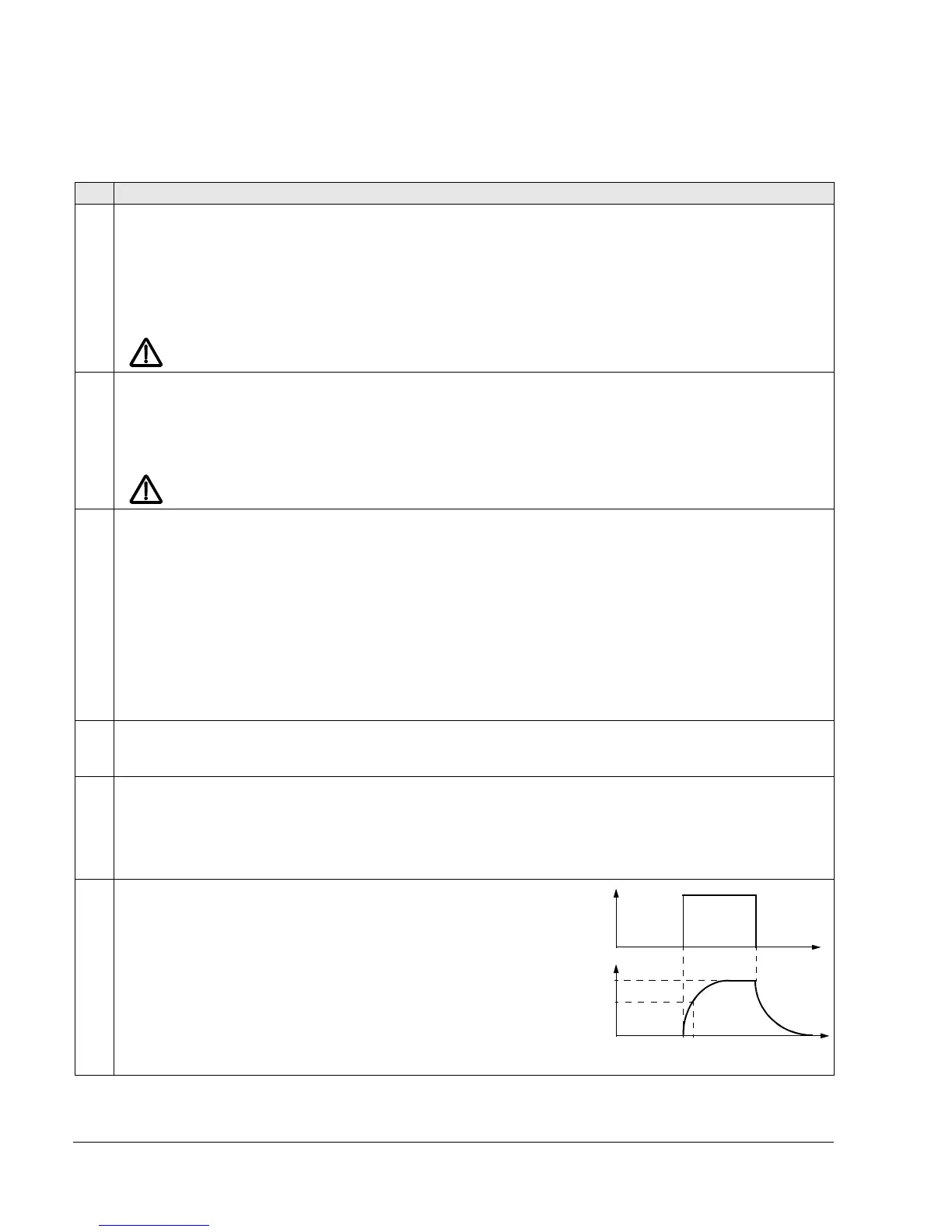
3006 MOT THERM TIME
Sets the motor thermal time constant for the motor temperature
model.
• This is the time required for the motor to reach 63% of the final
temperature with steady load.
• For thermal protection according to UL requirements for NEMA
class motors, use the rule of thumb:
MOTOR THERM TIME equals
35 times t6, where t6 (in seconds) is specified by the motor
manufacturer as the time that the motor can safely operate at six
times its rated current.
• The thermal time for a Class 10 trip curve is 350 s, for a Class
20 trip curve 700 s, and for a Class 30 trip curve 1050 s.
Temp. ri se
100%
63%
}
P 3006
Motor load
t
t

 Loading...


