ACS550-02/U2 User’s Manual 221
Embedded fieldbus
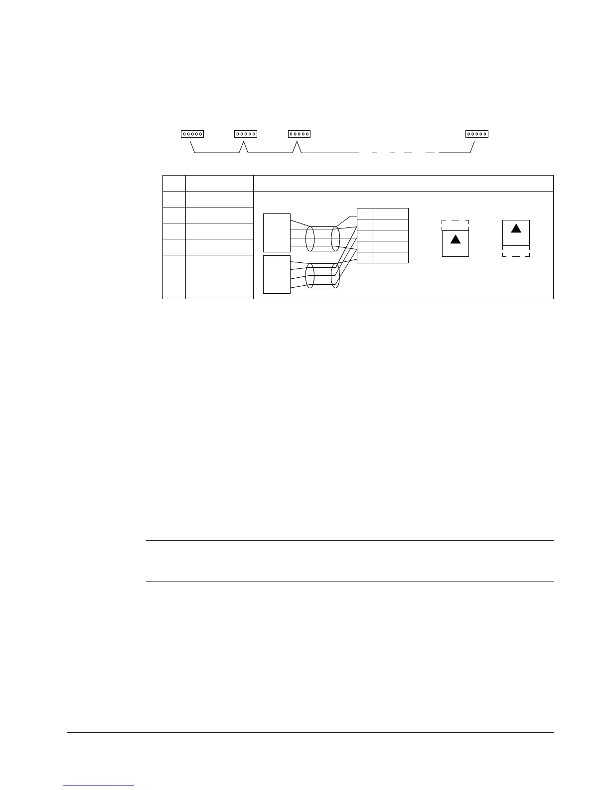
• To reduce noise on the network, terminate the RS485 network using 120 Ω
resistors at both ends of the network. Use the DIP switch to connect or disconnect
the termination resistors. See following diagram and table.
• Connect the shield at each end of the cable to a drive. On one end, connect the
shield to terminal 28, and on the other end connect to terminal 32. Do not connect
the incoming and outgoing cable shields to the same terminals, as that would
make the shielding continuous.
• For configuration information see the following sections:
– Communication set-up – EFB on page 221
– Activate drive control functions – EFB on page 223
– The appropriate EFB protocol specific technical data. For example, Modbus
protocol technical data on page 231.
Communication set-up – EFB
Serial communication selection
To activate the serial communication, set parameter 9802
COMM PROT SEL =
1(
STD MODBUS).
Note: If you cannot see the desired selection on the panel, your drive does not have
that protocol software in the application memory.
X1 Identification Hardware description
28 Screen
29 B (Positive +)
30 A (Negative -)
31 AGND
32 Screen
Terminated Terminated
station
Station Station
station
28 SCR
29 B
30 A
31 AGND
32 SCR
SCR
+
-
GND
RS485 Multidrop application
RS485 interface
Bus termination
OFF position ON position
SCR
+
-
GND
J2
ON
J2
ON

 Loading...


