246 ACS550-02/U2 User’s Manual
Embedded fieldbus
State diagram
ABB Drives profile
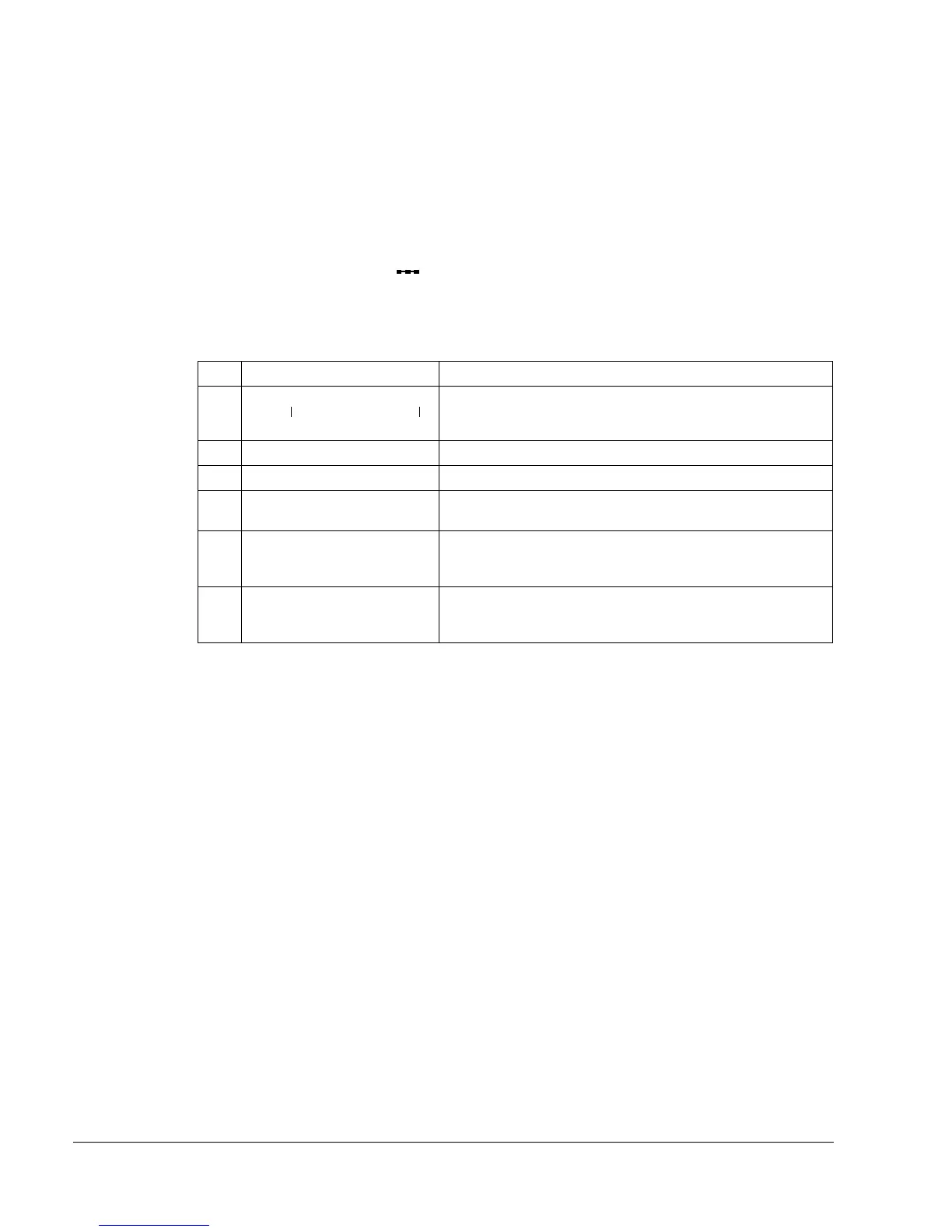
To illustrate the operation of the state diagram, the following example (
ABB DRV LIM
implementation of the ABB Drives profile) uses the control word to start the drive:
• First, the requirements for using the
CONTROL WORD must be met. See above.
• When the power is first connected, the state of the drive is not ready to switch on.
See dotted lined path ( ) in the state diagram below.
• Use the
CONTROL WORD to step through the state machine states until the
OPERATING state is reached, meaning that the drive is running and follows the
given reference. See the table below.
Step CONTROL WORD Value Description
1 CW = 0000 0000 0000 0110 This CW value changes the drive state to
READY TO SWITCH
ON.
2 Wait at least 100 ms before proceeding.
3 CW = 0000 0000 0000 0111 This CW value changes the drive state to READY TO OPERATE.
4 CW = 0000 0000 0000 1111 This CW value changes the drive state to
OPERATION ENABLED.
The drive starts, but will not accelerate.
5 CW = 0000 0000 0010 1111 This CW value releases the ramp function generator (RFG)
output and changes the drive state to RFG: ACCELERATOR
ENABLED.
6 CW = 0000 0000 0110 1111 This CW value releases the ramp function generator (RFG)
output and changes the drive state to
OPERATING. The drive
accelerates to the given reference and follows the reference.
bit 0bit 15

 Loading...


