ACS550-02/U2 User’s Manual 145
Parameters
Group 13: ANALOG INPUTS
This group defines the limits and the filtering for analog inputs.
Code Description
1301 MINIMUM AI1
Defines the minimum value of the analog input.
• Define value as a percent of the full analog signal range. See example below.
• The minimum analog input signal corresponds to 1104 REF1 MIN or 1107 REF2 MIN.
•
MINIMUM AI cannot be greater than MAXIMUM AI.
• These parameters (reference and analog min. and max. settings) provide scale and offset adjustment for the
reference.
• See the figure at parameter 1104.
Example. To set the minimum analog input value to 4 mA:
• Configure the analog input for 0…20 mA current signal.
• Calculate the minimum (4 mA) as a percent of full range (20 mA) = 4 mA / 20 mA · 100% = 20%
1302 MAXIMUM AI1
Defines the maximum value of the analog input.
• Define value as a percent of the full analog signal range.
• The maximum analog input signal corresponds to 1105
REF1 MAX or 1108 REF2 MAX.
• See the figure at parameter 1104.
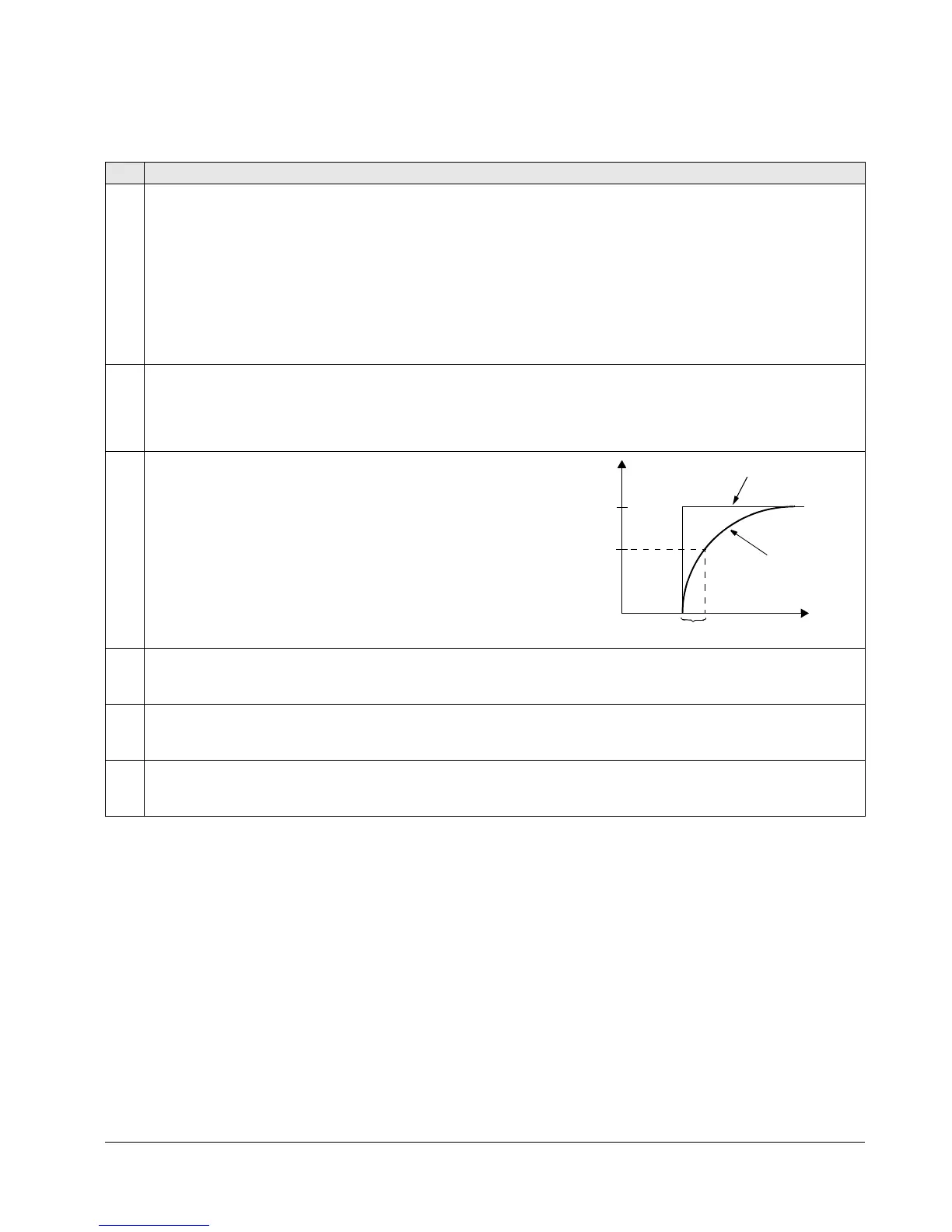
1303 FILTER AI1
Defines the filter time constant for analog input 1 (AI1).
• The filtered signal reaches 63% of a step change within the time
specified.
1304 MINIMUM AI2
Defines the minimum value of the analog input.
•See
MINIMUM AI1 above.
1305 MAXIMUM AI2
Defines the maximum value of the analog input.
•See
MAXIMUM AI1 above.
1306 FILTER AI2
Defines the filter time constant for analog input 2 (
AI2).
•See
FILTER AI1 above.
100
63
%
Unfiltered signal
Filtered signal
Time constant
t

 Loading...


