ACS550-02/U2 User’s Manual 47
Installation
Leading the power (input and motor) cables through the lead-through plate
1. Make adequate holes in the grommets to fit them tightly on the cables.
2. Lead the cables through the holes (all three conductors of a three-phase cable
through the same hole) and slide the grommets onto the cables.
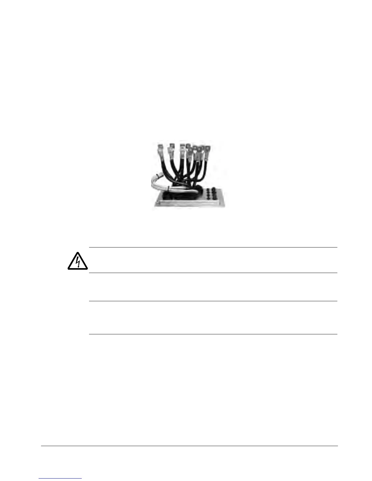
Preparing the power cables
1. Strip the cables.
2. Twist the shield wires.
3. Bend the conductors to the terminals.
4. Cut the conductors to adequate length. Put the pedestal onto the lead-through plate
and check the length of the conductors. Remove the pedestal.
5. Crimp or screw cable lugs onto the conductors.
WARNING! The maximum allowed width of the cable lug is 38 mm (1.5 in). Wider
cable lugs may cause a short-circuit.
6. Connect the twisted shields of the cables to the PE terminal (frame size R7), or to
the grounding clamps or PE terminal (frame size R8).
Note: 360 degrees grounding is not needed at the cable entry. The short twisted
shield provides, in addition to the protective grounding, also sufficient disturbance
suppression.

 Loading...


