ACS550-02/U2 User’s Manual 299
Technical data
Cable entries
Mains and motor cable maximum sizes (per phase) accepted at the cable terminals,
and the tightening torques are listed below.
Input power (mains) connection
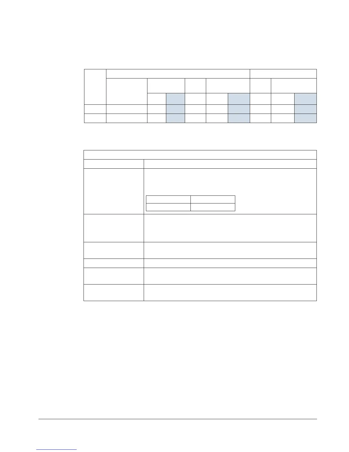
Frame
size
U1, V1, W1, U2, V2, W2 Earthing PE
Number of
cable lead-
through holes
per phase
Max. cable
diameter
Bolt
size
Tightening
torque
Bolt
size
Tightening
torque
mm
in N·m lbf·ft N·m lbf·ft
R7 2 58
2.28 M12 50…75 35…55 M8 15…22 10…16
R8 3 58
2.28 M12 50…75 35…55 M8 15…22 10…16
00467918.xls B
Input power (mains) connection specifications
Voltage (U
1
) 400/415/440/460/480 V AC 3-phase +10% -15% for 400 V AC drives
Short-circuit
withstand strength
(IEC 60439-1)
Maximum allowable prospective short-circuit current when protected by
IEC fuses given in the fuse table on page 295 is
for 02 drives: 65 kA (I
cc
)
for U2 drives (with enclosure extension):
Short-circuit current
protection (UL 508)
US and Canada: According to UL 508, the drive is suitable for use in a
circuit capable of delivering not more than 100 kA symmetrical amperes
(rms) at 600 V maximum when protected by UL fuses given in the fuse
table on page 295.
Frequency
48…63 Hz
Imbalance Max. ± 3% of nominal phase to phase input voltage
Fundamental power
factor (cos phi
1
)
0.98 (at nominal load)
Cable temperature
rating
70 °C (158 °F) rating minimum
I
cw
/ 1 s I
pk
50 kA 105 kA

 Loading...


