ACS550-02/U2 User’s Manual 51
Installation
Fixing the pedestal to the drive frame
1. Fix the fastening screws.
WARNING! The fixing is important because the screws are required for the
grounding of the drive.
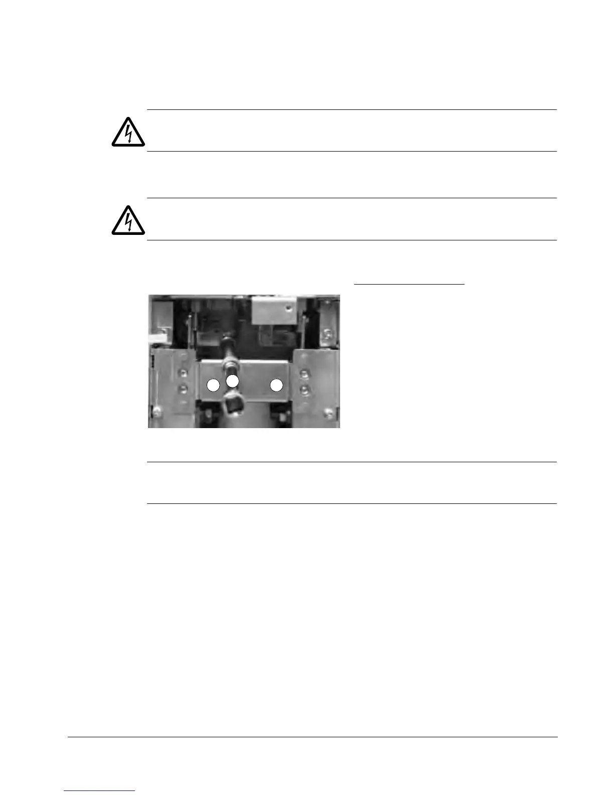
2. Connect the terminals at the top of the pedestal to the terminals at the bottom of the
upper part of the drive frame.
WARNING! Be careful not to drop screws inside the pedestal. Loose metal pieces
inside the drive may cause damage.
3. Tighten the connections.
4. Fasten the drive with screws or bolts to the holes in the wall.
Note: In mounting orientation a (see page 37), do not fasten the drive to a wall if it is
subjected to sideways vibration.
5. Connect the control cables as described in section Connecting the control cables on
page 54.
Fastening the covers
1. Connect the control panel cables.
2. Fasten the upper front cover.
3. Fasten the lower front covers.
Terminal connection screws
R7: M8 (5/16 in) combi screws
Tightening torque: 15…22 N·m (11…16 lbf·ft)
R8: M10 (3/8 in) combi screws
Tightening torque: 30…44 N·m (22…32 lbf·ft)
11
2
View of frame size R7

 Loading...


