110 ACS550-02/U2 User’s Manual
Application macros
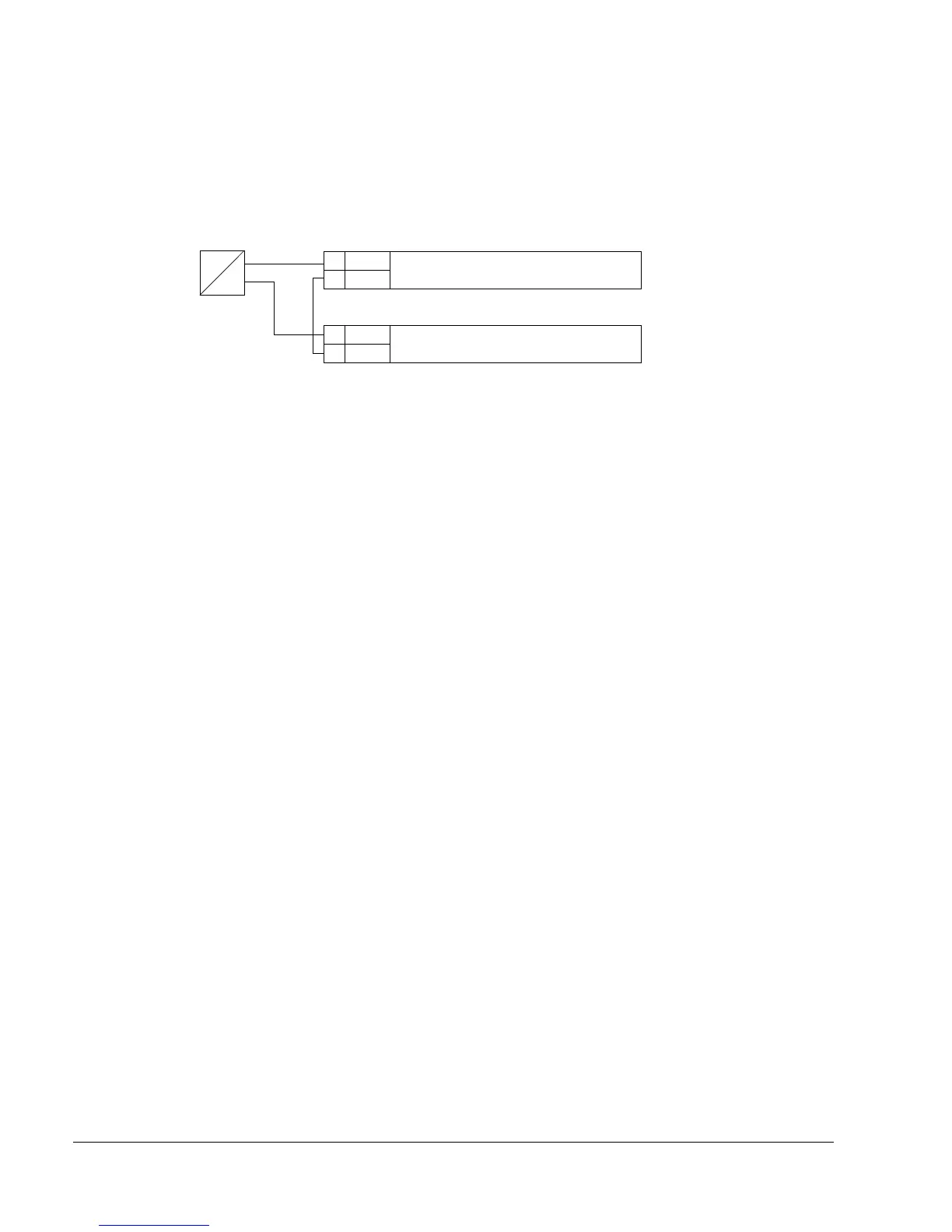
Connection example of a two-wire sensor
Many applications use process PI(D) and need a feedback signal from the process.
The feedback signal is typically connected to analog input 2 (AI2). The macro wiring
diagrams in this chapter show the connection when a separately powered sensor is
used. The figure below gives an example of a connection using a two-wire sensor.
Note: The sensor is supplied through its current output. Thus the output signal must
be 4…20 mA, not 0…20 m A.
X1 / control board
5 AI2 Process actual value measurement,
0(4) … 20 mA, R
in
= 100 ohm
6AGND
…
X1 / control board
10 +24 V Auxiliary voltage output, non-isolated,
24 V DC, 250 mA
11 GND
P
I
4…20 mA

 Loading...


