ACS550-02/U2 User’s Manual 177
Parameters
Group 34: PANEL DISPLAY
This group defines the content for control panel display (middle area), when the
control panel is in the Output mode.
Code Description
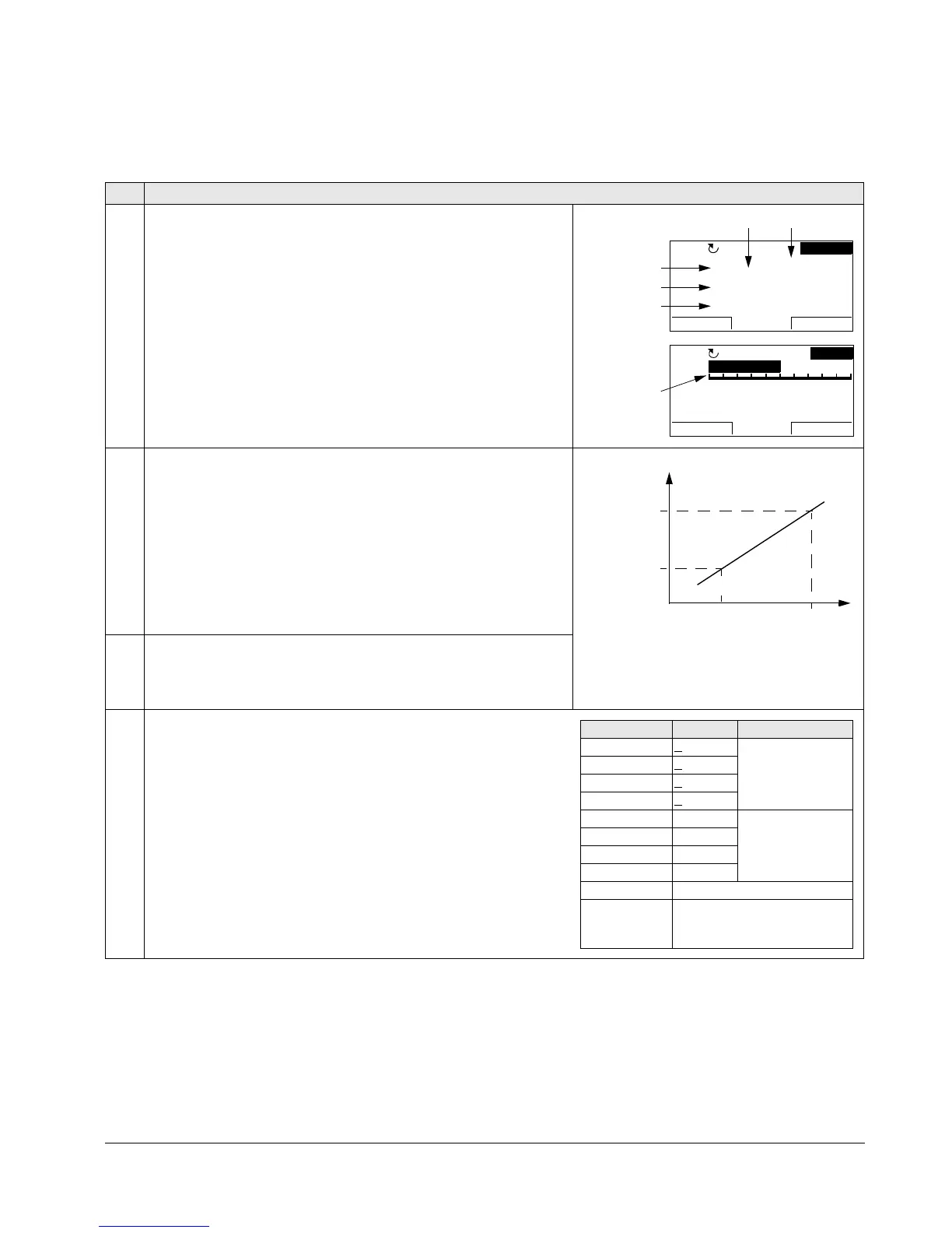
3401 SIGNAL1 PARAM
Selects the first parameter (by number) displayed on the control
panel.
• Definitions in this group define display content when the control
panel is in the control mode.
• Any parameter number in Group 01: OPERATING DATA can be
selected.
• Using the following parameters, the display value can be scaled,
converted to convenient units and/or displayed as a bar graph.
• The figure identifies selections made by parameters in this group.
100 =
NOT SELECTED – First parameter not displayed.
101…159 – Displays parameter 0101…0159. If parameter does not
exist, the display shows “n.a.”
3402 SIGNAL1 MIN
Defines the minimum expected value for the first display parameter.
Use parameters 3402, 3403, 3406 and 3407, for example to convert
a Group 01: OPERATING DATA parameter, such as 0102 SPEED (in
rpm) to the speed of a conveyor driven by the motor (in ft/min). For
such a conversion, the source values in the figure are the min. and
max. motor speed, and the display values are the corresponding min.
and max. conveyor speed. Use parameter 3405 to select the proper
units for the display.
Note: Selecting units does not convert values. Parameter is not
effective if parameter 3404
OUTPUT1 DSP FORM = 9 (DIRECT).
3403 SIGNAL1 MAX
Defines the maximum expected value for the first display parameter.
Note: Parameter is not effective if parameter 3404
OUTPUT1 DSP
FORM = 9 (DIRECT).
3404 OUTPUT1 DSP FORM
Defines the decimal point location for the first display parameter.
0…7 – Defines the decimal point location.
• Enter the number of digits desired to the right of the decimal
point.
• See the table for an example using pi (3.14159).
8 =
BAR METER – Specifies a bar meter display.
9 =
DIRECT – Decimal point location and units of measure are
identical to the source signal. See Group 01: OPERATING DATA
parameter listing in section Complete parameter list on page 115
for resolution (which indicates the decimal point location) and the
units of measure.
5 A
1 Hz
7 %10.
0.
49.
49.1Hz
LOC
DIR
MENU00:00
P 3404 P 3405
4 A
4 %24.
0.
5.0Hz
LOC
DIR
MENU00:00
HZ 50%
P 3404
P 3401 (137)
P 3408 (138)
P 3415 (139)
Source value
P 3407
P 3406
P 3403
P3402
Display
value
3404 value Display Range
0+ 3 -32768…+32767
(Signed)
1+
3.1
2+ 3.14
3+
3.142
4 3 0…65535
(Unsigned)
53.1
63.14
73.142
8 Bar meter displayed.
9 Decimal point location and
units as for the source
signal.

 Loading...


